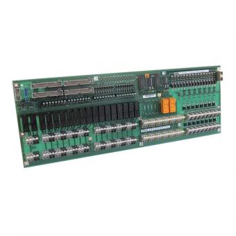
Description
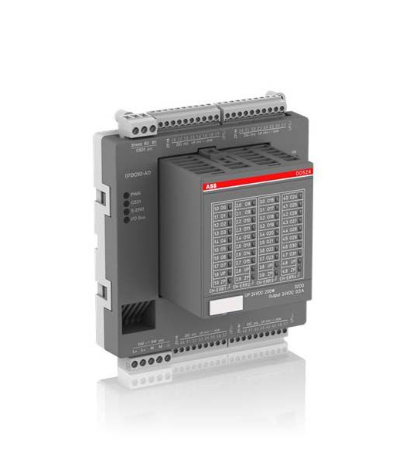
ABB DO526 1SAP240800R0001
I. Overview
ABB DO526 1SAP240800R0001 is a digital output module, which belongs to the supporting I/O module system of the S500 series programmable logic controllers (PLCs). It converts the digital logic signals output by the PLC master control unit into electrical signals with high-current driving capability, directly driving various high-load actuators on the industrial site. It realizes precise control and status feedback of industrial field devices, and serves as a key core component connecting the PLC control system and high-load field execution mechanisms.
Originating in Sweden, this module features excellent reliability and environmental adaptability. Adopting an industrial-grade transistor output architecture and optimized circuit design, it integrates multiple safety protection mechanisms and can operate stably in complex industrial environments. It is widely used in automated production lines of industries such as automobile manufacturing and food processing, can accurately meet the control requirements of complex technological processes, and provides reliable guarantee for the efficient and stable operation of automation systems. At present, the market supply channels are mature, which can fully meet the accessory supporting needs of industrial equipment maintenance and replacement, system upgrading and transformation, and new construction projects.
II. Product Features
High-current and High-load Driving Capability: Adopting a digital transistor output mode, it is equipped with 8 independent digital output channels. Each channel can provide an output specification of 24VDC with a maximum current of 2A, adopting a 1-wire system design. Compared with conventional low-current output modules, it can directly drive high-current load devices such as relays and solenoid valves without additional power amplification components, greatly simplifying the system construction process and adapting to the driving needs of various medium and high-power actuators.
High-reliability Safety Protection Design: Strictly complying with ABB's design standards for industrial automation products, it is equipped with a comprehensive safety protection mechanism. It has a built-in reverse voltage protection function, which can effectively prevent module damage caused by incorrect positive and negative wiring connections. Each module and output group adopts a current isolation design, which can completely eliminate the impact of strong on-site electromagnetic interference and ground potential difference on the module's core circuit and the PLC master control unit. Meanwhile, it is equipped with a 10A fast fuse, which can quickly cut off the circuit in case of overcurrent faults, avoiding the expansion of faults and damage to the module and external equipment, thus significantly improving the operation stability under complex working conditions.
Flexible Installation and Compact Structure: It supports two installation methods: horizontal and vertical, which can be flexibly adjusted according to the space layout in the on-site control cabinet to adapt to different installation scenarios. It should be noted that derating is required in accordance with technical specifications when installing vertically in an environment of +40℃. With a compact design, the module can be directly installed on a standard DIN rail, featuring convenient installation and effective space saving in the control cabinet. Its protection class reaches IP20, which can meet the installation and use requirements of standard industrial environments.
Excellent System Compatibility: As a dedicated supporting module for the ABB S500 series, it can be perfectly compatible with the same series of PLC master control units, realizing high-speed data interaction with the CPU through the backplane bus and ensuring the real-time transmission of control commands. The module supports flexible combination with other I/O modules in the series, and can realize local or remote expansion of up to 10 I/O modules. It can accurately meet the construction needs of automation systems of different scales and simplify the integration process of the overall control system.
- Convenient Operation, Maintenance and Debugging Experience: Adopting a modular plug-and-play design, it is easy to install and disassemble, enabling quick replacement and maintenance of the module. The module is equipped with clear channel status indicator lights, allowing operation and maintenance personnel to intuitively monitor the working status of each channel and quickly locate faulty channels, thus greatly shortening maintenance downtime. Meanwhile, the module debugging process is simple, and it can be put into use quickly without complex parameter configuration, reducing debugging difficulty and operation and maintenance costs.
III. Technical Parameters
1. Core Basic Parameters
- Product Model: DO526 1SAP240800R0001
- Product Series: Supporting I/O Module for ABB S500 Series Programmable Controllers
- Product Type: Industrial-grade Digital Output Module (Digital Transistor Output)
- Manufacturer: ABB (ASEA Brown Boveri)
- Place of Origin: Sweden
- Product Number: 1SAP240800R0001
- Mounting Method: Modular plug-and-play installation, supporting horizontal/vertical installation, compatible with standard DIN rails
- Expansion Capability: Supporting local or remote expansion, with a maximum expandable capacity of 10 I/O modules
- Core Functions: Digital signal conversion, high-current load driving, status monitoring, multiple fault protection
- Application Scenarios: Automated production lines in industries such as automobile manufacturing and food processing, suitable for driving and controlling high-load actuators such as relays and solenoid valves
2. Electrical Performance Parameters
- Working Power Supply Voltage: 20.4 - 28.8VDC (compatible with industrial standard power supply environment)
- Number of Output Channels: 8-channel digital output (independent channel design, supporting parallel output)
- Output Signal Type: Digital transistor output signal
- Output Voltage Range: 20.4 - 28.8VDC
- Output Current: Maximum 2A per channel
- Wiring Method: 1-wire system
- Isolation Method: Each module and output group is equipped with current isolation
- Protection Configuration: Equipped with a 10A fast fuse and reverse voltage protection function
3. Environmental and Physical Parameters
- Operating Temperature: -25℃ to +70℃ (wide-temperature design, suitable for extreme industrial environments); derating is required when installing vertically at +40℃
- Storage Temperature: -40℃ to +85℃
- Relative Humidity: 5% to 95% (no condensation)
- Protection Class: IP20 (module body, suitable for installation in control cabinets, dust-proof and solid foreign object intrusion prevention)
- Electromagnetic Compatibility: Compliant with industrial-grade electromagnetic compatibility standards, with strong anti-electromagnetic interference capability
- Module Dimensions: Depth 6.2cm, Height 7.6cm, Width 6.75cm (compact design, saving installation space)
- Weight: Net weight about 0.132kg, gross weight about 0.156kg
IV. Working Principle
The core working principle of the ABB DO526 1SAP240800R0001 digital output module is a closed-loop control process of "Signal Reception - Isolation and Conversion - Power Amplification - Load Driving - Status Monitoring - Feedback Transmission". Through the collaborative work of multiple internal functional units, it realizes the safe and accurate conversion and transmission of PLC control signals into high-load driving signals. The specific working process can be divided into six core stages:
Stage 1: Signal Reception StageThe module establishes a communication connection with the ABB S500 series PLC master control unit through the backplane bus, and receives the digital logic control signals (0/1) issued by the master control unit, which correspond to control commands such as "stop/start" for external high-load actuators. Meanwhile, it receives configuration commands from the master control unit to complete the initialization setting of parameters such as output mode and protection threshold.
Stage 2: Isolation and Conversion StageThe received control signals enter the internal current isolation unit. The dedicated isolation circuit realizes electrical isolation between the input control signals and the output driving circuit, effectively avoiding the impact of strong on-site electromagnetic interference and ground potential difference on the PLC master control unit and the module's core circuit. The isolated signals are processed by the shaping and filtering circuit and converted into stable driving control signals, preparing for subsequent power amplification.
Stage 3: Power Amplification StageThe control signals after isolation and conversion enter the power amplification unit. The internal high-performance transistor amplifies the weak signals into electrical signals with high-current driving capability (24VDC, maximum 2A), meeting the driving needs of high-load devices such as relays and solenoid valves.
Stage 4: Load Driving StageThe amplified driving signals are transmitted to external high-load actuators through 8 independent output channels, driving the actuators to complete corresponding actions (pull-in, start-stop, etc.). Meanwhile, the 10A fast fuse at the front end of the channel monitors the circuit current in real time. In case of overcurrent faults, the fuse can quickly blow to cut off the circuit and protect the module and external equipment.
Stage 5: Status Monitoring StageThe module is equipped with a built-in channel status monitoring circuit and power reverse connection monitoring circuit, which collect the voltage and current signals of each output channel in real time to determine whether there are faults such as overcurrent, short circuit and open circuit in the output channels. Meanwhile, it monitors the power connection status of the module. If positive and negative reverse connection occurs, the reverse connection protection mechanism is activated immediately to cut off the power circuit and prevent module damage.
Stage 6: Feedback Transmission StageThe working status of each output channel (normal driving/fault), power status and the module's own operation status data are fed back to the PLC master control unit through the backplane bus. If a fault is detected, the fault alarm mechanism is triggered immediately to report the fault information to the master control unit, facilitating the system to execute protection logic in a timely manner. At the same time, the fault is intuitively indicated through the module status indicator light, making it convenient for operation and maintenance personnel to troubleshoot and handle the fault.
V. Common Fault Troubleshooting
1. No Output from Channels/High-load Devices Fail to Operate
Phenomenon: One or more output channels have no driving signal output, and the corresponding external high-load actuators (such as relays, solenoid valves) fail to operate; the PLC master control unit displays "normal output", but the on-site devices have no response; the status indicator light of the corresponding channel of the module is not on.
Causes: Loose, poor contact or wrong wiring between the module and external actuators (such as positive and negative reverse connection triggering reverse connection protection); failure of external high-load actuators (such as burnt relay coils, jammed solenoid valves); blown 10A fast fuse of the module's output channel; failure of the module's internal transistor power amplification circuit; abnormal working power supply voltage of the module (lower than 20.4VDC or higher than 28.8VDC) or power supply interruption.
Solutions: 1. Disconnect the module power supply, check the wiring between the corresponding channels and external devices, correct wrong wiring, re-plug and fasten the wiring connectors, replace damaged and aging lines, and ensure reliable connection. 2. Test the performance of external high-load actuators separately, connect a standard 24VDC, 2A power supply to the devices to verify whether they can operate normally, and replace the devices with the same model if they are faulty. 3. Use a multimeter to measure the working power supply voltage of the module to ensure the voltage is stable within the range of 20.4 - 28.8VDC, and repair the power supply fluctuation or power supply interruption problem. 4. After disconnecting the power supply, check the 10A fast fuse of the corresponding channel; if the fuse is blown, replace it with a fuse of the same specification and power on again for testing. 5. If the above measures are ineffective, the module's internal transistor power amplification circuit is most likely faulty, and it is necessary to contact professional maintenance personnel or ABB official after-sales service for inspection and repair.
2. Abnormal Output from Channels/Misoperation of Actuators
Phenomenon: The output channel signals fluctuate frequently, causing frequent start-stop and misoperation of external high-load actuators; the channel has output signals when the PLC master control unit does not issue control commands; the status indicator light of the corresponding channel of the module flashes frequently.
Causes: Excessively strong electromagnetic interference in the industrial field (such as radiation interference generated by frequency converters and high-power motors); signal lines not using shielded cables, or shielded layers not grounded or poorly grounded; module grounding terminal not reliably grounded, and the grounding loop is incomplete; failure of the module's internal isolation circuit, leading to signal crosstalk; abnormal output signals of the PLC master control unit; excessive fluctuation of the module's working power supply voltage.
Solutions: 1. Replace the output lines with shielded cables, adopt single-end grounding for the shielded layer (grounding resistance ≤4Ω), separate the signal lines from power cables (spacing at least 30cm), and keep away from strong electromagnetic interference sources such as frequency converters and high-power relays. 2. Check the wiring of the corresponding channels, re-fasten the connectors, replace aging and damaged lines to ensure no virtual connection in the wiring. 3. Check the grounding condition of the module, ensure that the module grounding terminal is reliably grounded, improve the system grounding loop, and reduce ground potential interference. 4. Check the output signal of the PLC master control unit; if the output of the master control unit is abnormal, troubleshoot the fault of the master control unit. 5. Measure the working power supply voltage of the module; if the fluctuation is excessive, install a power filter device to ensure the voltage is stable within the rated range. 6. If the above measures are ineffective, the module's internal isolation circuit may be faulty, and it is necessary to contact professional personnel for inspection, repair or module replacement.
3. Module Fails to Communicate with PLC Master Control Unit
Phenomenon: After the module is connected to the PLC system, it cannot establish a communication connection with the master control unit; the PLC master control unit displays fault prompts such as "module lost" and "communication link interrupted"; the communication status indicator light of the module is not on or flashes the fault light constantly.
Causes: Loose, poor contact or wrong wiring of the backplane bus between the module and the PLC master control unit; incorrect module address setting, resulting in address conflict with other modules in the system; abnormal working power supply voltage of the module, leading to the failure of the communication circuit to work normally; failure of the module's internal communication chip; on-site electromagnetic interference affecting the transmission of communication signals; the number of system expansion modules exceeding the rated limit of 10.
Solutions: 1. Disconnect the power supply, check the wiring of the backplane bus between the module and the PLC master control unit, correct wrong wiring, fasten loose connectors, and replace damaged communication cables. 2. Check and correct the module address through PLC configuration software or module DIP switches to ensure it is consistent with the address configured in the system and avoid address conflict. 3. Use a multimeter to measure the working power supply voltage of the module to ensure the voltage is stable within the rated range and repair the power supply fault. 4. Check the number of system expansion modules; if it exceeds the rated limit of 10, reduce the number of modules or add expansion links. 5. Restart the module and the PLC master control unit to re-establish the communication connection. 6. If the communication still fails, the module's internal communication chip may be faulty, and it is necessary to contact ABB official after-sales service for inspection and repair.
4. Module Overheating/Frequent Fuse Blowing
Phenomenon: The surface temperature of the module rises rapidly during operation, exceeding the normal working temperature range; the output channel fuses blow frequently, triggering equipment shutdown; the module overheating alarm indicator light is always on (if equipped).
Causes: The load current of external actuators exceeds the rated 2A limit of the channel, leading to module overload; no derating is performed when installing vertically in an environment of +40℃, resulting in poor heat dissipation; poor ventilation at the module installation location, and the heat dissipation channel is blocked, leading to heat accumulation; excessively high working power supply voltage of the module, resulting in increased energy consumption of the internal circuit; multiple output channels driving high-load devices at the same time, and the total power consumption exceeding the module's bearing capacity.
Solutions: 1. Disconnect the module power supply immediately, check the load current of the external devices connected to each output channel to ensure it does not exceed the rated 2A limit, replace the overloaded devices or add a power amplification link. 2. If installing vertically in an environment of +40℃, reduce the load or adjust the installation method (change to horizontal installation) in accordance with technical specifications. 3. Clean dust and debris on and around the module to ensure unobstructed heat dissipation channels, do not block the heat dissipation vents of the module, and keep the module at a safe distance of at least 30cm from high-power heat-generating equipment. 4. Use a multimeter to measure the input power supply voltage to ensure stable output within the range of 20.4 - 28.8VDC and repair the problem of excessively high voltage. 5. Reasonably distribute the load of each channel, avoid multiple channels driving ultra-high-load devices at the same time, and reduce the total power consumption of the module. 6. If the module still overheats frequently or the fuse blows after taking the above measures, the internal power circuit may be faulty, and it is necessary to stop using the module immediately and contact professional maintenance personnel for treatment.
![]()