Description
Praxis 98.6.022.672
I. Overview
Taking the warehousing sorting system as an example, this module can be connected to devices such as photoelectric sensors at sorting to identify the position of goods and limit switches of push cylinders (to feedback the completion status of actions), and transmit information such as goods arrival signals and mechanical action status to the control system in real time; at the same time, according to the sorting instructions of the control system, it controls the actions of executive components such as push cylinders and conveyor belt steering motors through output channels to ensure that goods are accurately diverted to target areas, improving sorting efficiency and accuracy.
II. Technical Parameters
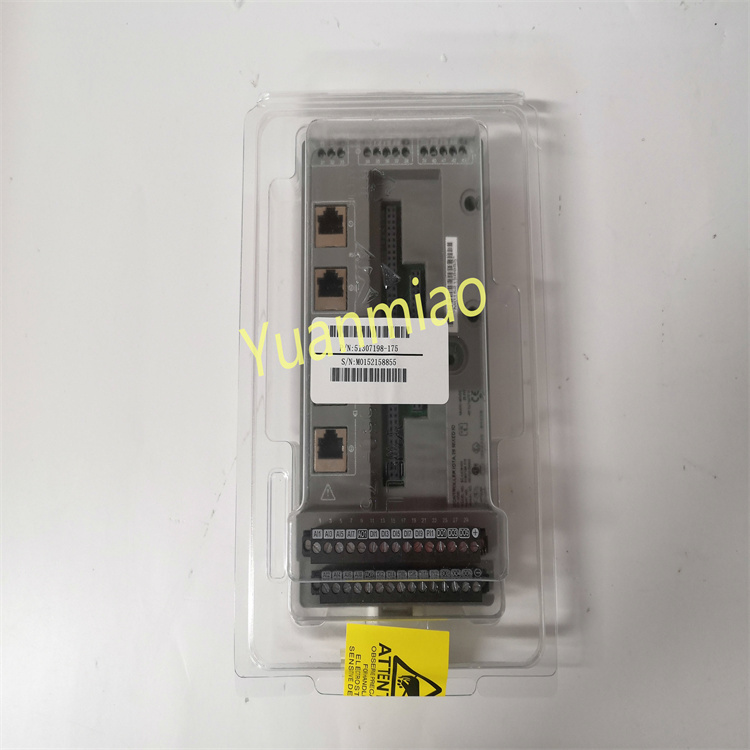
Digital input channels: Equipped with 20 digital input channels, supporting dry contacts and NPN/PNP type wet contact signals. The input voltage range is 10-30V DC, and the response time is ≤ 0.5ms, which can quickly capture the switch status changes of external equipment, meeting the signal collection needs of multiple devices.
Digital output channels: There are 12 digital output channels, each with a maximum output current of 2A and an output voltage of 24V DC. It supports short-circuit protection (self-recovery type) and can directly drive loads such as medium-sized solenoid valves, small contactors, and stepping motor drivers.
Isolation performance: Enhanced photoelectric isolation is adopted between input, output and power supply. The isolation voltage is ≥ 2500V AC (for 1 minute), and the isolation voltage between channels is ≥ 1000V AC, which effectively resists electromagnetic interference in industrial sites and ensures the accuracy of signal transmission.
Environmental adaptability: The operating temperature range is -20°C to +75°C, and the relative humidity is 5%-95% (no condensation), which can operate stably in complex environments such as low-temperature workshops and high-temperature drying areas; it can withstand vibration of 10-500Hz with an acceleration of 10g and impact of 20g (11ms half-sine wave), adapting to vibration and impact during equipment operation.
Communication interface: Integrate 1 RS-485 communication interface, supporting MODBUS RTU protocol. The data transmission rate can be adjusted between 1200bps and 38400bps, compatible with mainstream PLCs, industrial controllers and other equipment, realizing efficient data interaction.
Dimensions: Adopt DIN rail mounting design, with dimensions of 110mm × 80mm × 65mm (length × width × height). The structure is compact, saving installation space in the control cabinet, and suitable for intensive layout.
Protection level: The protection level reaches IP20, which can effectively prevent dust intrusion and finger contact with internal circuits, and is suitable for safe installation and use in control cabinets.
III. Functional Features
High-speed signal response and driving capability: The response time of the input channel is ≤ 0.5ms, which can quickly capture the subtle state changes of the equipment, ensuring that the control system obtains key information in time; the maximum driving current of the output channel is 2A, which can directly drive medium-power loads without additional power amplifier modules, improving control efficiency.
Enhanced anti-interference and reliability: Through high-voltage isolation design and independent isolation between channels, the anti-electromagnetic interference capability is significantly improved, and it can still work stably in environments with strong interference sources such as frequency converters and high-frequency motors; the self-recovery short-circuit protection function can quickly cut off the output when the load is short-circuited, and automatically recover after the fault is eliminated, reducing manual intervention.
Flexible compatibility and convenient integration: Support MODBUS RTU communication protocol, which can seamlessly connect with automation equipment of different brands, adapting to diversified control system architectures; the standard DIN rail mounting method makes the installation process simple and fast, and can quickly integrate into the existing system, shortening the debugging cycle.
Intuitive status monitoring: The surface of the module is equipped with LED status indicators for each input and output channel, as well as power and communication status indicators, which can display the working status of each channel and the overall operation of the module in real time, facilitating operators to quickly judge whether the equipment connection is normal and troubleshoot faults.
IV. Common Faults and Solutions
Possible causes: The input signal cable is too long, resulting in signal attenuation; the input channel is subject to strong electromagnetic interference; the working temperature of the module exceeds the normal range; the input signal voltage is close to the lower limit (10V DC).
Solutions: Shorten the length of the input signal cable or use shielded twisted pair; keep the signal cable away from strong interference sources (such as transformers, motors) and ensure the shield layer is grounded; improve the ventilation and heat dissipation conditions of the module's working environment to ensure the temperature is within the range of -20°C to +75°C; adjust the output voltage of the signal source to ensure it is not lower than 12V DC.
Frequent triggering of output channel protection
Possible causes: The actual working current of the load exceeds the rated value of 2A; the load has instantaneous surge current; poor contact of the output channel wiring leads to local overheating; abnormal sensitivity of the protection circuit.
Solutions: Detect the working current of the load, replace with a suitable low-power load or add an intermediate relay; connect a surge absorber (such as a varistor) in parallel at the load end to suppress instantaneous current; re-tighten the output terminals, remove the oxide layer to ensure good contact; if the protection circuit is abnormal, contact the manufacturer for firmware upgrade or replace the module.
Communication data loss or disorder
Possible causes: The RS-485 bus terminal resistor is not matched (120Ω is recommended); the communication baud rate is set too high, resulting in unstable signal transmission; there is a conflict in device addresses on the bus; the shield layer of the communication cable is not grounded at one end.
Solutions: Add 120Ω terminal resistors at both ends of the bus; reduce the communication baud rate to below 19200bps for testing; reset the device addresses to ensure unique addresses on the bus; ground the shield layer of the communication cable at one end (connected to the control cabinet grounding bar).
Abnormal flickering of module indicators
Possible causes: Unstable power supply voltage or pulse interference; abnormal operation of the module's internal program; potential short circuit in input/output channels; failure of communication protocol handshake.
Solutions: Add a filter capacitor (100μF/50V) at the power input end to suppress interference; power off and restart the module, and upgrade the firmware if frequent abnormalities occur; disconnect the loads of input/output channels one by one to check and repair the short-circuit channel; reconfigure the communication protocol parameters to ensure they are consistent with the upper computer.