Description
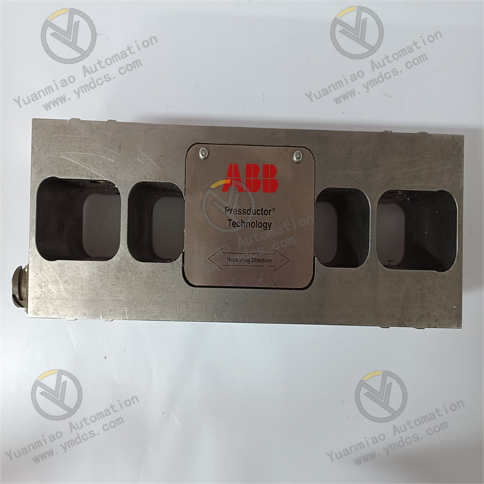
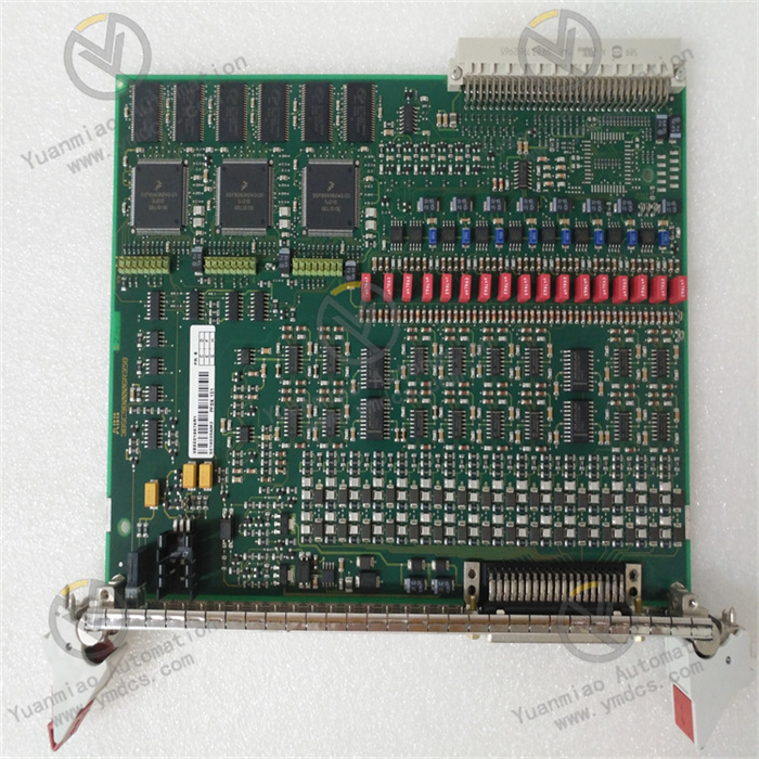
ABB S-093N 3BHB009885R0021
I. Overview
The ABB S-093N (Model: 3BHB009885R0021) is a redundant DC power supply module developed by ABB specifically for industrial high-reliability power supply scenarios. As a core supporting component of ABB control system series such as Advant and Symphony, its core positioning is to provide stable and clean DC power for industrial PLCs, DCS systems, servo drives, and precision sensors, undertaking the integrated functions of "AC rectification + voltage regulation + redundant backup + fault protection".Adopting a "high-frequency switching power supply topology + full isolation design", the module covers a wide range of AC input voltages and provides high-precision DC output. It features resistance to power grid fluctuations, strong electromagnetic interference suppression, and overload/short-circuit protection capabilities, enabling stable operation in industrial environments ranging from -10°C to +55°C. Certified by IEC 61010-1 (electrical safety) and EN 61326-1 (electromagnetic compatibility), it is widely applicable to large industrial equipment in power, metallurgy, petrochemical, and municipal fields (e.g., steam turbine control systems, rolling mill drive units, reactor monitoring systems). It provides "uninterrupted and highly stable" power supply guarantee for the continuous operation of industrial systems, while being compatible with ABB's own control systems and third-party industrial equipment, allowing seamless integration into existing automation systems.
II. Functional Features
1. Wide Input Range and High-Precision Output for Complex Power Grid Environments
The module supports a wide AC input voltage range of 85-264V AC (50/60Hz auto-adaptive), compatible with power grid specifications in different regions worldwide (e.g., 220V AC in China, 110V AC in the United States). It can withstand ±15% fluctuations in grid voltage (e.g., voltage dips caused by motor start/stop) without the need for additional voltage stabilizers. The output terminal adopts "high-frequency PWM voltage regulation + multi-stage filtering" technology, with an output voltage accuracy controlled within ±0.5% and a ripple coefficient ≤50mV P-P. It can directly supply power to precision equipment such as I/O modules of ABB Symphony DCS and CPU units of Siemens S7-400 PLC, avoiding program disorders or data acquisition deviations caused by voltage fluctuations.
2. Redundant Parallel Capability for Uninterrupted Power Supply
It supports 1+1 or N+1 redundant parallel operation. When multiple modules are connected in parallel, the built-in current-sharing control circuit realizes automatic load sharing with a current-sharing error ≤3%, allowing flexible expansion of output power according to system power demand (e.g., two parallel modules double the output power). When one module exits operation due to a fault (e.g., over-temperature, over-current), the remaining modules can take over the full load within ≤10ms, with no voltage drop during switching, ensuring uninterrupted operation of downstream equipment (e.g., steam turbine protection systems). For example, in the boiler control system of a thermal power plant, two S-093N modules supply power in parallel—even if one fails, the power supply safety of critical links such as fuel valve control and water level monitoring remains guaranteed.
3. Multi-Dimensional Protection Mechanism for Equipment and System Safety
It has a built-in three-level protection system covering "input - output - self":
- Input side: Overvoltage protection (triggered at 280V AC), undervoltage protection (triggered at 80V AC), and surge protection (±4kV line-to-ground) to resist abnormal grid impacts.
- Output side: Overcurrent protection (triggered at 1.2 times the rated current, hiccup mode), short-circuit protection (automatic recovery), and overvoltage protection (triggered at 1.1 times the rated voltage) to prevent module damage caused by downstream equipment faults.
- Self-protection: Over-temperature protection (triggered at 65°C, automatic derating operation) and fan fault protection (natural heat dissipation overload protection for fanless models) to prevent component aging due to long-term high-temperature operation of the module.
Meanwhile, the module is equipped with LED status indicators (e.g., "PWR - Power Normal", "FAULT - Fault", "RED - Redundancy Status") for intuitive display of operating status. In case of a fault, it outputs an alarm signal through a dry contact to facilitate quick problem localization.
4. Strong Anti-Interference and High-Reliability Design for Harsh Industrial Environments
The circuit adopts an "optical isolation + EMC filtering" design and passes the EN 61326-1 electromagnetic compatibility test, capable of resisting strong electromagnetic interference such as inverter harmonics and motor radiation. The output ripple can still be controlled within 50mV in high-interference environments. The housing in contact with fluids is made of cold-rolled steel plate (with anti-corrosion powder coating), resistant to acid and alkali corrosion, and suitable for harsh environments such as dust in metallurgical plants and humidity in chemical plants. Key components (e.g., capacitors, IGBTs) are industrial-grade products that undergo 1000-hour high-temperature aging tests, with a Mean Time Between Failures (MTBF) ≥80,000 hours, meeting the requirements of long-cycle continuous industrial production.
5. Easy Installation and System Integration to Reduce O&M Costs
It is compatible with standard 35mm DIN rail installation and uses a snap-on fixing structure, enabling installation and disassembly without tools. The input and output terminals adopt a screw-type design, supporting 10-16AWG wire connection, with clear terminal markings (e.g., "L-N-PE" for input, "+24V-GND" for output) to reduce the risk of wiring errors. The module is compatible with ABB Control Builder software, allowing remote monitoring of output voltage, current, and fault information via the RS485 interface (Modbus RTU protocol), and supporting online firmware upgrades without on-site shutdown operations, significantly reducing O&M time.
III. Technical Parameters
| Parameter Category | Specific Specifications | Remarks |
|---|---|---|
| Input Parameters | Input Voltage: 85-264V AC (single-phase), 50/60Hz (auto-adaptive) | Wide-voltage design, compatible with global power grids |
| Input Current: Maximum 3A (115V AC), 1.5A (230V AC) | Low input current, reducing power grid load | |
| Power Factor: ≥0.9 (full load, 230V AC) | High power factor, reducing reactive power loss, meeting industrial energy-saving requirements | |
| Input Protection: Overvoltage (280V AC), Undervoltage (80V AC), Surge (±4kV line-to-ground) | IEC 61000-4-5 standard surge protection | |
| Output Parameters | Output Voltage: 24V DC (default), 12V DC/48V DC (customizable) | Voltage accuracy ±0.5%, supporting software fine-tuning (±5%) |
| Output Current: Rated 10A (output power 240W at 24V DC) | Overload capacity: 1.2 times rated current for 1 minute | |
| Output Ripple: ≤50mV P-P | Measured within 20Hz-20MHz bandwidth | |
| Output Protection: Overcurrent (triggered at 12A), Short-circuit (automatic recovery), Overvoltage (triggered at 26.4V DC) | Overcurrent adopts "hiccup mode", automatic power recovery after short-circuit elimination | |
| Redundancy Characteristics | Redundancy Mode: Supports 1+1/N+1 parallel connection, current-sharing error ≤3% | Requires connection via inter-module current-sharing control line (RJ45 interface) |
| Redundancy Switching Time: ≤10ms | Fault module switching is imperceptible, no voltage drop | |
| Physical & Environmental | Housing Material: Cold-rolled steel plate (powder-coated surface) | Protection class IP20, suitable for installation inside control cabinets |
| Dimensions: 120mm×80mm×60mm (Length×Width×Height, DIN rail-mounted model) | Compact design, saving control cabinet space | |
| Weight: Approximately 0.8kg (fanless natural heat dissipation model) | Lightweight structure, facilitating rail installation | |
| Operating Temperature: -10°C to +55°C, Storage Temperature: -40°C to +85°C | Automatic derating in high-temperature environments (55°C-65°C), output power linearly reduced to 80% | |
| Heat Dissipation: Natural heat dissipation (low-power models) / Forced fan cooling (high-power models) | Derating protection triggered in case of fan failure to prevent module overheating | |
| Communication & Control | Communication Interface: RS485 (Modbus RTU), configurable baud rate 1200-115200bps | Supports remote monitoring of voltage, current, fault information, and firmware upgrades |
| Alarm Output: 1 dry contact (closed in case of fault), rated 250V AC/1A | Can be connected to PLC/DCS systems for remote fault alarm | |
| Safety Certifications | Electrical Safety: IEC 61010-1, Electromagnetic Compatibility: EN 61326-1 | Complies with industrial equipment safety and anti-interference standards |
IV. Working Principle
The ABB S-093N (3BHB009885R0021) realizes the power conversion process of "AC → DC → stable DC" based on high-frequency switching power supply technology, with the core workflow divided into four steps:
- Input Rectification and Filtering: The AC input (85-264V AC) passes through an EMC filter (to suppress grid interference), is converted into pulsating DC by a bridge rectifier circuit, and then filtered by a large-capacity electrolytic capacitor to obtain stable high-voltage DC (approximately 300V DC).
- High-Frequency Inversion: The high-voltage DC drives the IGBT switch through a PWM (Pulse Width Modulation) controller, converting it into high-frequency AC (20-50kHz). The high-frequency design reduces the transformer size and improves power supply efficiency (efficiency ≥88%).
- Isolated Voltage Transformation and Rectification: The high-frequency AC is stepped down by a high-frequency isolation transformer (with turns ratio adjusted according to output voltage requirements), then converted into low-voltage DC by a fast-recovery diode. The transformer also provides electrical isolation between input and output (isolation voltage 2500V DC) to ensure the safety of downstream equipment.
- Output Voltage Regulation and Filtering: The low-voltage DC passes through an LC filter circuit (to reduce ripple), and the output voltage is sampled in real time by a voltage feedback circuit. The PWM duty cycle is adjusted by comparing with the reference voltage, finally stabilizing the output voltage at 24V DC ±0.5%. Meanwhile, the current-sharing control circuit realizes load sharing when multiple modules are connected in parallel.
During redundant operation, multiple modules exchange output current information in real time through the current-sharing control line, and adjust their respective outputs via "master-slave control" or "average current control" algorithms to ensure uniform load distribution and avoid overload of a single module. In case of a fault, the faulty module exits quickly via a hardware signal, and the remaining modules take over the load through a current compensation algorithm to achieve uninterrupted power supply.
V. Power Supply Requirements of Steam Turbine Control Systems and Module Adaptability
1. Core Power Supply Pain Points
The steam turbine control system (including DEH digital electro-hydraulic control system and TSI safety monitoring system) is the "core control unit" of thermal power units. Its power supply system needs to address three core issues:
- Uninterrupted Requirement: A power supply interruption of more than 20ms to the servo valves of the main steam valve and regulating steam valve may cause unit load shedding or even shutdown.
- High-Precision Requirement: Equipment such as speed sensors (accuracy ±1r/min) and displacement transmitters are sensitive to power supply ripple (requiring ≤50mV P-P), otherwise measurement deviations will occur.
- High-Interference Environment: High-voltage motors, inverters, and other interference sources exist in the steam turbine plant, requiring resistance to ±4kV surges and harmonic interference.
2. Adaptability Advantages of ABB S-093N
| Requirement Dimension | Core Adaptability Features of the Module | Application Value Example |
|---|---|---|
| Power Supply Continuity | 1+1 redundant parallel connection, switching time ≤10ms, current-sharing error ≤3% | When a single module fails, the remaining modules take over the load seamlessly, avoiding steam valve misoperation caused by power loss of the EH oil system servo valves |
| Output Precision | 24V DC output accuracy ±0.5%, ripple ≤50mV P-P | Ensures stable data of TSI system vibration sensors, avoiding false alarms due to speed fluctuations |
| Anti-Interference Capability | EMC filtering + optical isolation, EN 61326-1 certification, surge protection ±4kV | Resists harmonic interference generated by feedwater pump inverters, ensuring normal operation of DEH logic operation units |
| Environmental Adaptability | Operating temperature -10°C to +55°C, MTBF ≥80,000 hours | Adapts to high-temperature and dusty environments in steam turbine plants, meeting the long-cycle requirement of 8,000 hours of annual unit operation |
Special Design of System Architecture
1. Redundant Power Supply Topology (Recommended Scheme)
A "dual independent input + 1+1 redundant parallel" architecture is adopted to meet the separate power supply requirements of DEH and TSI systems:plaintext
[Plant Power System] ├─ Unit Operating Section A (Main Power Supply) → Isolation Transformer → ABB S-093N Module 1 └─ Unit Operating Section B (Backup Power Supply) → Isolation Transformer → ABB S-093N Module 2 ↓ (Connected via RJ45 current-sharing control line) [Parallel Output Bus] → DC Distribution Panel → Shunt Power Supply ├─ DEH Control Cabinet: Servo Valve Driver, CPU Module, I/O Unit ├─ TSI Control Cabinet: Speed/Vibration Sensor, Signal Conditioning Module └─ EH Oil System: Pressure Transmitter, Accumulator Pressure Monitoring Unit
- Key Design: The input power is taken from different bus sections (referring to the load distribution logic of Bulian Project) to avoid overall power loss caused by a single bus section fault. A 20A DC circuit breaker is configured on the output side to provide independent protection for each load circuit.
2. Communication and Alarm Integration
- Data Interaction: Connect to the unit DCS system via the RS485 interface (Modbus RTU protocol), uploading parameters including output voltage (accuracy ±0.1V), load current (±0.1A), module temperature, and redundancy status.
- Alarm Linkage: The dry contact alarm signal is connected to the DEH emergency shutdown circuit. When the module's "FAULT" light is on, it triggers a DCS alarm pop-up window and links with sound and light alarms, while prohibiting unit load increase operations.
Module Selection and Capacity Calculation
1. Selection Principles
- Redundancy Level: 1+1 redundancy is adopted for units with a single-machine capacity ≤300MW; N+1 redundancy is recommended for units ≥600MW (e.g., 3 modules in parallel, 2 in operation and 1 standby).
- Input Adaptation: For domestic power plants, select the 220V AC input model, equipped with a 1kVA isolation transformer (primary-secondary insulation 2500V DC).
- Heat Dissipation Selection: When the number of modules in the control cabinet is ≥3, select the forced fan cooling model, combined with an axial fan inside the cabinet (air volume ≥100m³/h).
2. Capacity Calculation Example (600MW Unit DEH System)
| Load Type | Quantity | Power Consumption per Unit | Total Power Consumption | Redundancy Factor | Calculated Capacity | Recommended Configuration |
|---|---|---|---|---|---|---|
| DEH CPU Module | 2 | 15W | 30W | 1.2 | 36W | |
| Servo Valve Driver | 6 | 20W | 120W | 1.2 | 144W | |
| TSI Sensor Group | 8 | 5W | 40W | 1.2 | 48W | |
| Auxiliary Control Unit | 4 | 10W | 40W | 1.2 | 48W | |
| Total | - | - | 230W | 1.2 | 276W | 2 parallel 240W modules |
VI. Special Specifications for Installation and Wiring
1. Installation Environment Requirements
2. Key Points for Wiring Operation
Commissioning and Acceptance Process
1. Pre-Power-On Inspection
2. Phased Commissioning
Phase 1: Single Module Test (with Redundancy Line Disconnected)
Phase 2: Redundancy Function Test
Phase 3: Anti-Interference Test
3. Acceptance Criteria
Operation, Maintenance and Troubleshooting
1. Key Points for Daily Operation and Maintenance
2. Typical Troubleshooting (Special for Steam Turbine Scenarios)
Adaptation Case with Domestic DEH System