Description
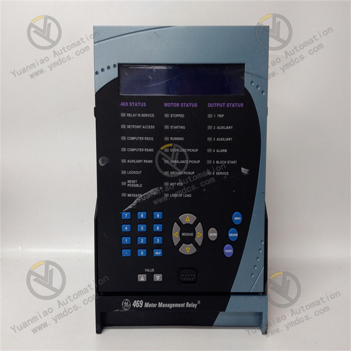
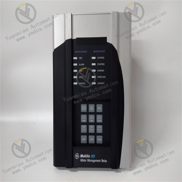
GE Multilin 369-HI-R-M-0-0-0-E
Overview
As a high-performance motor management relay in the GE Multilin series, the GE Multilin 369-HI-R-M-0-0-0-E is specially designed for industrial environments, committed to providing comprehensive protection and monitoring for medium to large three-phase motors and their related systems. With its excellent reliability and versatility, this relay plays a crucial role in numerous fields such as industrial automation, power systems, and building automation, effectively ensuring stable and efficient motor operation and facilitating the smooth progress of various industrial production activities.
Functional Features
Comprehensive Motor Protection Functions
- Electrical Fault Protection:
- Equipped with precise overload protection, it continuously monitors motor current. Once the current exceeds the preset overload threshold and persists for the corresponding duration, it immediately triggers a trip action to fully prevent the motor from damage due to overheating.
- It can acutely detect undervoltage. When the power supply voltage is lower than the specified level, it can choose to trip according to actual needs to avoid motor stalling due to insufficient power, and can also automatically restart the motor after the voltage recovers to normal.
- It has reliable overvoltage protection. When the voltage exceeds the upper limit, it quickly cuts off the connection between the motor and the power supply, effectively protecting the motor insulation from breakdown.
- In addition, for short-circuit faults, the relay can quickly respond and trip within milliseconds to avoid serious damage to the motor and other electrical components.
- It can also accurately identify ground faults, effectively building a defense line for system and personnel safety.
- It can real-time monitor the unbalance of three-phase current to detect potential problems of motor windings or other components in a timely manner.
- Mechanical Fault Monitoring:
- Through the close monitoring of motor acceleration time and current characteristics, it can acutely sense mechanical blockages such as blocked fans or 卡死 (seized) bearings, and take effective protective measures in a timely manner.
- It is equipped with 12 optional RTD (Resistance Temperature Detector) input interfaces, which are used to real-time monitor the temperature of stator windings and bearings. Once abnormal temperature rise occurs, it can immediately trigger an alarm or trip to prevent motor faults in advance and minimize losses.
Powerful Real-time Monitoring Capabilities
- Real-time Parameter Measurement: It continuously measures various electrical parameters during motor operation with extremely high precision, including voltage, current, power (covering kW, kVA, kvar), power factor, and frequency, etc. These real-time data are like a "barometer" of the motor operation status, providing indispensable key basis for system operation analysis, energy management, and predictive maintenance.
- Event Recording and Logging: It has excellent event recording functions and can thoroughly store a large amount of event information such as trips, alarms, and changes in operating conditions. The detailed event logs are like a "key" after a fault occurs, helping to deeply analyze the root cause, and then optimize the system operation and maintenance strategies to improve the overall system performance.
Flexible Configuration Options
- Parameter Adaptive Learning: The relay has an intelligent "learning" function, which can automatically adjust and adapt to specific motor parameters according to the actual operation of the motor, such as inrush current during startup, cooling rate during operation, and acceleration time, etc., to achieve more precise personalized protection and control, just like tailoring a set of exclusive "protection solutions" for each motor.
- Customizable Settings: Users can not only easily enter the menu system through the front-panel buttons of the device to set some basic parameters such as CT and VT ratios, enabling or disabling of protection functions, and alarm thresholds, etc. They can also use the special Enervista 369 setup software (used with a computer) to achieve flexible configuration of more advanced parameters such as protection curves, communication protocols, and event recording options, etc., fully meeting the diversified needs of different motors and application scenarios.
Technical Parameters
| Category | Specifications |
|---|---|
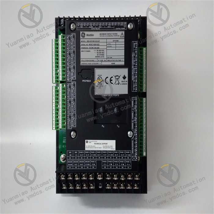
| Control Power | DC: 50 - 300 VDC AC: 60 - 265 VAC, 50/60 Hz Nominal Power: 20 VA; Maximum Power: 65 VA |
| Current Input | Suitable for 50/60 Hz rated frequency, measurement range is 0.05 - 20 × CT primary side amperes, using true RMS measurement, sampling rate 1.04 ms/sample |
| RTD Input | 12 optional RTD input interfaces, RTD types can be customized by users |
| Output | 4 alarm outputs, 2 trip outputs (non-fault safety trip: 200 ms; fault safety trip: 100 ms) |
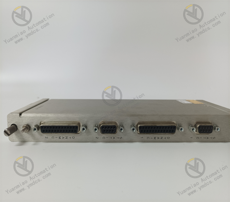
| Communication | 1 front-panel RS232 port, 3 rear-panel RS485 ports, supporting standard Modbus RTU protocol; optional communication interfaces such as Modbus/TCP, Profibus - DP, Profibus - DPv1, DeviceNet, etc. can be configured, and users can customize the baud rate (1200 - 19200) |
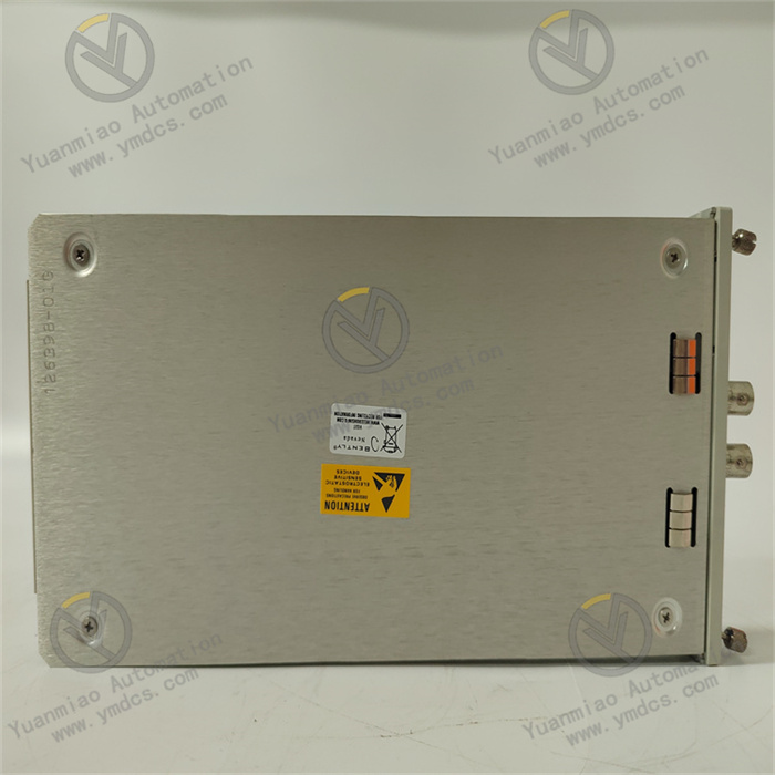
| Dimensions | Approximately 144 mm (height) × 168 mm (width) × 222 mm (length) |
| Weight | Approximately 4.5 kg |
| Environmental Requirements | Operating temperature: -25°C to +70°C; Storage temperature: -40°C to +85°C; Humidity: 5% - 95% RH (non-condensing) |
Working Principle
Protection Logic Operation
The relay continuously and closely monitors the input signals from current transformers (CT), voltage transformers (VT), and RTD. In terms of electrical protection, it compares the real-time measured values of current, voltage, power, etc., with the pre-carefully set protection thresholds one by one. For example, when the monitored current amplitude exceeds the overcurrent protection setting value and the duration exceeds the set trip time, the protection logic will quickly respond, trigger the trip output, make the relevant circuit breaker act, and decisively isolate the motor from the power supply, thus successfully protecting the motor from damage. In terms of mechanical protection, it accurately judges the mechanical condition by deeply analyzing the parameter changes in the motor operation process. For example, it carefully monitors the actual acceleration time of the motor and makes a detailed comparison with the expected acceleration time. If the actual acceleration time exceeds the expected range, it will determine that a mechanical blockage may have occurred and immediately start the corresponding protection measures to ensure the safety of the motor.
Data Acquisition and Processing
The analog signals output by the current transformer and voltage transformer are first converted into digital quantities by a high-precision analog-to-digital converter (ADC), and then handed over to the microprocessor for in-depth processing. The microprocessor uses precise algorithms to accurately calculate key parameters of the motor such as power, power factor, and frequency based on the sampled current and voltage data. At the same time, the temperature data from the RTD will also be timely collected and processed. The resistance value of the RTD will change with the temperature, and the internal circuit of the relay cleverly converts this resistance change into the corresponding digital temperature value, and compares it with the set temperature threshold for the purpose of protection and monitoring, providing comprehensive and accurate data support for the evaluation of the motor operation status.
Communication and Interface Functions
With the help of RS232 and RS485 communication ports, the relay can carry out efficient and stable data interaction with other devices in the system, such as the supervisory control and data acquisition (SCADA) system. Based on the standard Modbus RTU protocol, the relay can quickly send real-time measurement data (such as motor operation parameters, event logs, etc.) to external devices, and at the same time, timely receive configuration commands from the outside to achieve remote monitoring and control. If optional communication interfaces are configured, the connection capability of the relay will be further expanded, and it can be more smoothly integrated into different industrial network architectures, significantly improving the efficiency of remote monitoring and control and providing users with a more convenient and efficient use experience.
Operation Guide
Installation Steps
- Selection and Fixing of Installation Location: The relay can be conveniently installed in a standard 19-inch cabinet or a suitable electrical enclosure. It should be particularly noted that the installation location should be kept away from strong electromagnetic interference sources to ensure the normal and stable operation of the equipment. When installing, use the attached installation brackets and screws to firmly fix the relay in the selected position to prevent it from loosening during operation.
- Wiring Operations:
- Power Connection: According to the system requirements, accurately connect the wires of the control power supply (DC or AC) to the designated power terminals of the relay. For DC power, it is necessary to strictly pay attention to the positive and negative polarities to avoid reverse connection; for AC power, ensure that the phase sequence is correct to guarantee the stability of the power supply.
- Connection of Current and Voltage Inputs: Connect the secondary wires of the current transformer and voltage transformer to the corresponding input terminals of the relay, and ensure that the CT and VT are correctly grounded to effectively prevent the occurrence of electrical accidents and ensure the safety of equipment and personnel.
- RTD Connection: If RTD is used for temperature monitoring, connect the RTD wires to the 12 RTD input terminals. In this process, special attention should be paid to using the correct type of RTD wires and strictly following the correct wiring method to ensure the accuracy of temperature measurement and provide reliable data for motor temperature monitoring.
- Output Connection: Connect the alarm and trip output wires to the corresponding control devices, such as alarm indicators or circuit breakers, to ensure that alarms can be timely issued and trip protection measures can be taken in case of abnormal situations.
Configuration Methods
- Local Configuration: Use the front-panel buttons of the relay to easily enter the menu system, where some basic parameters such as CT and VT ratios, enabling or disabling of protection functions, and alarm thresholds, etc., can be conveniently set to meet the user's initial personalized setting needs for the equipment.
- Remote Configuration: Connect the computer to the relay through the RS232 or RS485 port using the Enervista 369 setup software. The software provides a more comprehensive, convenient, and intuitive interface, which can be used to configure advanced parameters such as protection curves, communication protocols, and event recording options, etc., providing users with more in-depth and detailed equipment configuration services.
Fault Troubleshooting
- Power Problems: If the relay cannot be powered on, first carefully check whether the power connection is firm, check whether the fuse is blown, and confirm that the control power supply voltage is within the specified range to ensure the normal power supply.
- False Tripping Problems: Recomprehensively check the protection parameter settings to ensure that they are accurately matched with the actual operating conditions of the motor. At the same time, carefully check whether the wiring of the current and voltage input circuits is loose or damaged, because these problems are very likely to lead to inaccurate measurements, and then cause false tripping phenomena, affecting the normal operation of the equipment.
- Communication Failures: If there is a problem with data communication, first confirm that the cable connection between the relay and external devices is normal. Then, carefully check whether the communication parameter settings (such as baud rate, protocol, etc.) are consistent on the relay and the connected device. If optional communication interfaces are used, it is also necessary to ensure that the additional hardware and software configurations are correct to ensure smooth communication.