Description
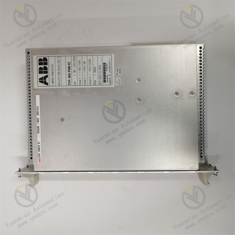
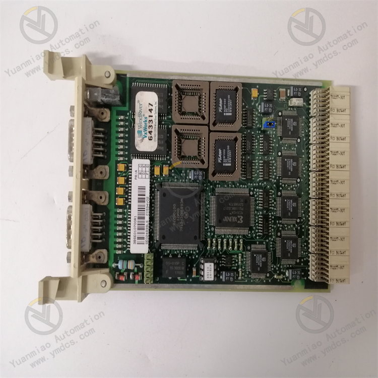
Bombardier DCC2223A 3EST125-977
Bombardier DCC2223A 3EST125-977 is a Programmable Logic Controller (PLC). As a core control component of industrial automation control systems, it features powerful programmable capabilities and stable operational performance. Its core positioning is to realize automated control of industrial equipment and production processes through precise logic operations and signal processing. It can be widely adapted to the control requirements of various fields such as power systems, rail transit auxiliary equipment, industrial production lines, and large electromechanical equipment. It provides reliable command execution and data interaction support for complex control systems, ensuring the efficient and stable operation of industrial systems.
I. Product Features
1. High-performance Programmable Control for Complex Scenario Requirements
2. Modular Expansion Design with Strong System Adaptability
3. Industrial-grade Reliable Design with Excellent Environmental Adaptability
4. Convenient Operation & Maintenance and Configuration to Reduce Usage Costs
5. Rich Communication Interfaces Supporting Multi-device Collaboration
II. Technical Parameters
1. Basic Parameters
- Model: Bombardier DCC2223A 3EST125-977
- Product Type: Programmable Logic Controller (PLC)
- Core Functions: Logic control, sequence control, process control, signal acquisition and processing, remote communication
- Programming Languages: Ladder Diagram (LD), Function Block Diagram (FBD), Statement List (STL)
- Programming Method: Programming via dedicated configuration software
- Expansion Capability: Supporting multiple expansion modules such as digital I/O, analog, and communication modules
- Compatible Systems: Bombardier series control equipment, mainstream industrial SCADA systems
- Installation Method: DIN rail mounting / panel mounting
2. Electrical Parameters
- Supply Voltage: 24V DC ±10%
- Power Consumption: Typical value ≤15W, maximum ≤20W
- Digital Input: Supporting 16 channels of standard digital inputs, input voltage 24V DC
- Digital Output: Supporting 16 channels of standard digital outputs, output type relay/transistor (optional)
- Analog Input: Supporting 8 channels of analog inputs, compatible with 4~20mA current signals and 0~10V voltage signals, resolution 12-bit
- Analog Output: Supporting 4 channels of analog outputs, output range 4~20mA current signals and 0~10V voltage signals, accuracy ±0.1%FS
- Communication Interfaces: RS-485, Ethernet (RJ45), USB
- Communication Rate: RS-485 interface up to 115.2 kbps, Ethernet interface 10/100Mbps
- Program Storage Capacity: ≥8MB
- Data Storage Capacity: ≥2MB
3. Environmental Parameters
- Operating Temperature: -20℃~+65℃
- Storage Temperature: -40℃~+85℃
- Relative Humidity: 5%~95%RH (non-condensing)
- Vibration Resistance: Compliant with IEC 60068-2-6 standard (10~500Hz, acceleration 5g)
- Shock Resistance: Compliant with IEC 60068-2-27 standard (peak acceleration 30g, duration 11ms)
- Electromagnetic Compatibility: Compliant with EN 55011 and EN 55022 industrial electromagnetic interference protection standards
- Protection Rating: IP20 (when mounted on DIN rail)
4. Physical Parameters
- Dimensions: 180mm×120mm×80mm (L×W×H, excluding mounting parts)
- Net Weight: Approximately 0.8kg~1.0kg
- Housing Material: Industrial-grade flame-retardant plastic
- Terminal Type: Plug-in phoenix terminals, facilitating wiring and maintenance
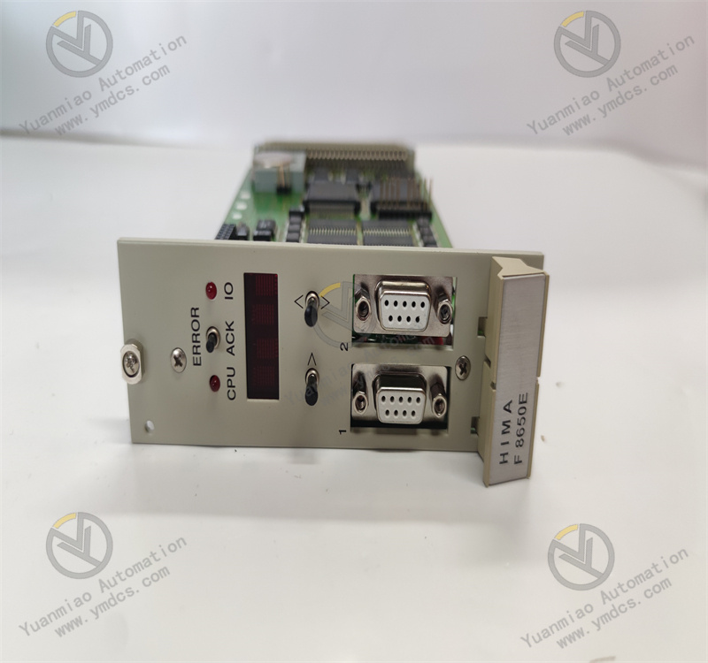
- Status Indicators: Power light (PWR), Run light (RUN), Fault light (FAULT), Communication status light (COMM), I/O status indicators
III. Working Principle
The core working logic of the Bombardier DCC2223A 3EST125-977 Programmable Logic Controller is "Power Supply - Program Loading - Signal Acquisition - Logic Operation - Command Output - Status Monitoring". It realizes automated control of industrial systems through the collaboration of multiple links, with the specific workflow as follows:
- Power Supply and System Initialization: The controller is connected to a standard 24V DC power supply. The internal power module performs voltage stabilization, filtering, and reverse polarity protection to provide stable power for core components such as the processor, memory, I/O interfaces, and communication modules. At the same time, it automatically loads preset system parameters and user-written control programs, completes hardware self-test and system initialization, and enters the operation-ready state after passing the self-test.
- Signal Acquisition and Data Processing: It real-time collects status signals and detection data from field devices such as sensors and limit switches through digital/analog input interfaces, converts analog signals into digital signals, and transmits them to the processor. The internal signal processing circuit performs filtering and noise reduction on the collected signals to eliminate interference signals, ensuring the accuracy and stability of data acquisition.
- Logic Operation and Control Decision-making: Based on the loaded control program, the processor performs logic operations, comparison judgments, and sequential execution on the collected field data, and generates corresponding control commands in combination with preset control thresholds and logical relationships. For example, in a production line control scenario, according to the material position signal detected by the sensor, it judges whether to execute the next conveying and processing commands; in a power system, it adjusts the actuator action to stabilize parameters according to voltage and current detection data.
- Command Output and Execution Control: The generated control commands are transmitted to actuators such as relays, solenoid valves, and frequency converters through digital/analog output interfaces, driving the actuators to complete corresponding actions to achieve precise control of industrial equipment or production processes. At the same time, the control commands and equipment operation status data are transmitted to the upper system through communication interfaces to realize real-time monitoring of the control process.
- Status Monitoring and Fault Diagnosis: The system real-time monitors its own working status (such as power supply voltage, program running status, module connection status) and field device feedback signals, and identifies abnormal conditions (such as signal loss, actuator failure, program error, communication interruption, etc.) through built-in diagnostic logic. When a fault is detected, it immediately turns on the fault indicator, records the fault code and fault occurrence time in the internal memory, and sends alarm information to the upper system through the communication interface. If necessary, it triggers the safety protection mechanism to stop the operation of related equipment to avoid fault expansion.
IV. Common Fault Troubleshooting
| Fault Phenomenon | Possible Causes | Troubleshooting and Solutions |
|---|---|---|
| Power light not on, controller unresponsive | Abnormal supply voltage; reversed power polarity; poor contact of power supply lines; internal power module failure | Use a multimeter to measure the supply voltage to ensure it is 24V DC±10%; check the positive and negative power connections to avoid polarity reversal; inspect the terminal connections of the power supply lines, re-plug and tighten them, and check for terminal oxidation or line damage; if the power supply and wiring are normal but the controller is still unresponsive, judge that the internal power module is faulty and contact after-sales service for repair or replacement. |
| Program cannot be uploaded/downloaded, configuration failed | Damaged/poor contact of communication cables; mismatched communication parameters; incompatible configuration software version; USB/Ethernet interface failure | Replace the communication cable, re-plug the interface to ensure firm contact; check that the communication parameters (baud rate, address, protocol type) of the controller and configuration software are consistent; upgrade the configuration software to a version compatible with the controller; use a multimeter to measure the interface pin voltage; if abnormal, judge that the interface is faulty and contact after-sales service for repair. |
| Abnormal input signal acquisition, inaccurate data | Sensor failure; poor shielding/disconnection of input signal cables; signal interference; input channel failure | Test the sensor separately to confirm that the sensor output signal is normal; replace the input signal cable with a twisted-pair shielded cable, keep it away from strong interference sources such as frequency converters and high-voltage cables, and ensure the shield layer is reliably grounded; check whether the signal cable is disconnected or short-circuited and repair the damaged line; if the sensor and cable are normal, switch the signal to a spare input channel; if it returns to normal, judge that the original input channel is faulty and the module needs to be repaired or replaced. |
| No response to output commands, actuator not operating | Output channel failure; actuator failure; poor contact of output cables; overcurrent protection triggered | Use a multimeter to detect the output signal of the controller to judge whether the output channel is normal; test the actuator (such as relay, solenoid valve) to confirm that its power supply and operation are normal; check the output cable connection, re-plug and tighten the terminals; if overcurrent protection is triggered, check whether the actuator is stuck causing current over-limit, clean foreign objects and reset the protection device; replace the actuator if necessary. |
| Communication interrupted, unable to interact with upper system | Incorrect communication protocol selection; mismatched communication parameters; communication module failure; abnormal network topology | Confirm that the communication protocol selected by the controller and the upper system is consistent (e.g., both are Modbus); check the communication address, baud rate, data bits/stop bits and other parameters, reconfigure and test; replace the spare communication module; if communication is restored, judge that the original module is faulty; check the network topology to eliminate device address conflicts; if it is Ethernet communication, ensure that the IP address is in the same network segment. |
| Controller restarts frequently or crashes | Excessive fluctuation of power supply voltage; program error/infinite loop; excessively high ambient temperature/poor heat dissipation; loose modules | Install a regulated power supply or UPS to ensure stable supply voltage; check the control program to troubleshoot infinite loops and logic errors, modify and re-download the program; check the controller installation environment, avoid close contact with heat-generating equipment to ensure smooth heat dissipation; power off and re-plug all modules to ensure firm connection; if the problem persists, contact after-sales service to test the core components. |