Description
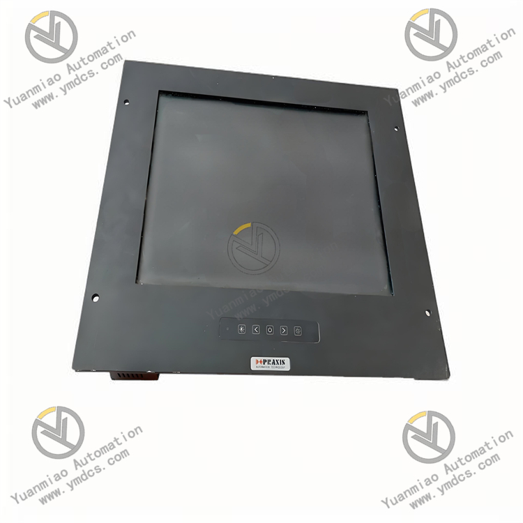
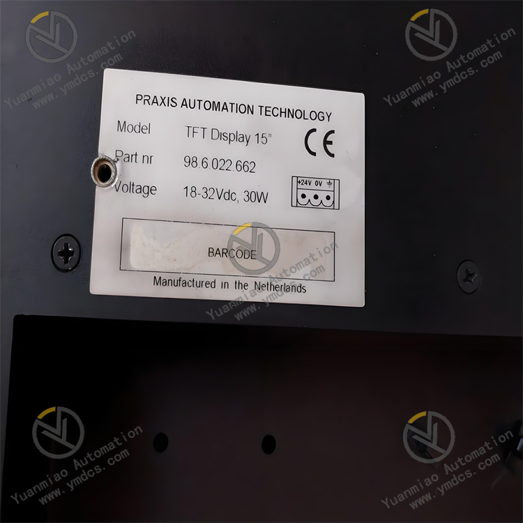
Praxis 98.6.022.662
I. Overview
Taking packaging equipment as an example, this module can be connected to devices such as photoelectric sensors (to detect whether materials are in place) and travel switches (to detect the position of robotic arms) of the packaging machine, collect the switch status signals of these devices in real time, and transmit the signals to the control system; at the same time, it receives instructions from the control system and controls the start and stop of executive components such as the sealing device of the packaging machine and the conveyor belt motor through the output channel, ensuring the orderly progress of the packaging process and improving packaging efficiency and accuracy.
II. Technical Parameters
Digital input channels: Equipped with 16 digital input channels, supporting dry contacts and NPN type wet contact signals. The input voltage range is 10-30V DC, and the response time is ≤ 1ms, which can quickly capture the switch status changes of external equipment, meeting the signal acquisition needs of small and medium-sized systems.
Digital output channels: Has 16 digital output channels, each with a maximum output current of 1.5A and an output voltage of 24V DC, supporting short-circuit protection (fuse type), and can directly drive loads such as small solenoid valves, indicator lights, and micro motors.
Isolation performance: Basic optoelectronic isolation is adopted between input, output and power supply, with an isolation voltage ≥ 2000V AC (for 1 minute), which can effectively reduce the impact of electromagnetic interference in industrial sites on the normal operation of the module.
Environmental adaptability: The operating temperature range is -10°C to +70°C, and the relative humidity is 5%-95% (no condensation), which can operate stably in general industrial environments; it can withstand vibration of 10-500Hz with an acceleration of 5g and impact of 10g (11ms half-sine wave), adapting to the vibration environment of small and medium-sized equipment.
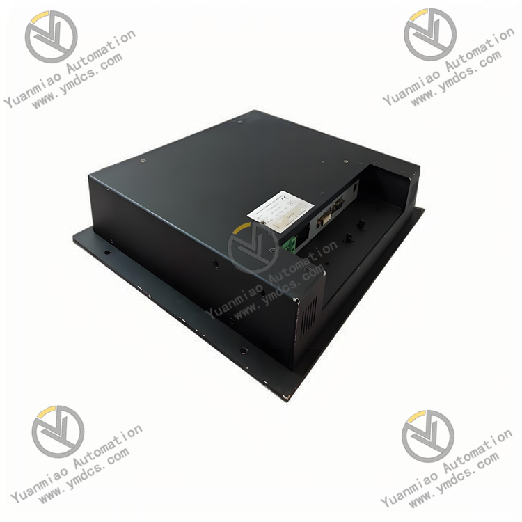
Communication interface: Integrates 1 RS-485 communication interface, supporting MODBUS RTU protocol. The data transmission rate can be selected between 2400bps and 19200bps, facilitating data interaction with PLCs, human-machine interfaces and other equipment to realize centralized control.
Dimensions: Adopts DIN rail mounting design, with dimensions of 100mm×75mm×60mm (length × width × height). It is small in size, saving installation space in the control cabinet, and suitable for the compact layout of small and medium-sized control systems.
Protection level: The protection level reaches IP20, which can effectively prevent fingers or other solid foreign objects from entering the module, and is suitable for installation in control cabinets.
III. Functional Features
Stable and reliable signal processing: Although it adopts a basic isolation design, it can still ensure the stability of signal transmission in general industrial electromagnetic environments. The input response time is ≤ 1ms, which can timely capture changes in equipment status, ensuring that the control system can respond quickly.
Convenient system integration: Supports MODBUS RTU communication protocol, which can be easily connected with mainstream PLCs, industrial computers and other equipment without complex protocol conversion; the standard DIN rail mounting method makes the installation process simple and fast, and can be quickly integrated into the existing control system.
Economical and practical: Designed for small and medium-sized systems, it effectively controls costs on the premise of meeting basic functional requirements. At the same time, the module has a low failure rate and low maintenance cost, providing users with a cost-effective automation solution.
Clear status indication: The surface of the module is equipped with status indicators for input and output channels, which can intuitively display the working status of each channel, facilitating operators to quickly judge the connection and operation status between the module and external equipment, and facilitating fault troubleshooting.
IV. Common Faults and Solutions
Possible causes: The signal of the external device is not output normally; the wiring of the input channel is loose or in poor contact; the input signal voltage is not within the range of 10-30V DC; the input channel is damaged.
Solutions: Check whether the external equipment is working normally to ensure the signal is output normally; re-plug and fasten the wiring of the input channel; use a multimeter to measure the input signal voltage to ensure it is within the specified range; switch the signal to other standby input channels, if it is normal, it indicates that the original channel is damaged, and the module can be replaced or the standby channel can be used.
The output channel cannot drive the load
Possible causes: Incorrect wiring of the output channel; the load current exceeds 1.5A, causing the fuse to blow; the drive circuit of the output channel is damaged; the load is short-circuited.
Solutions: Check the wiring of the output channel to ensure the positive and negative poles are connected correctly; replace the blown fuse, and check the load current at the same time, if it exceeds the rated value, an intermediate relay needs to be added to expand the load capacity; use a multimeter to detect the conductivity of the output channel, and if the drive circuit is confirmed to be damaged, replace the module; check whether the load is short-circuited, and connect the module after repair.
Unstable communication
Possible causes: Poor contact or aging of RS-485 communication cables; incorrect settings of communication parameters (baud rate, address, etc.); too many devices on the bus or too long distance; presence of electromagnetic interference.
Solutions: Check the connection of communication cables and replace aging cables; check and unify the communication parameters of the module and the communication object; reduce the number of devices on the bus, or add RS-485 repeaters; keep the communication cables away from strong interference sources (such as motors, frequency converters), and use shielded cables to ensure the shield layer is grounded.
The module cannot be powered on
Possible causes: Abnormal power supply voltage (not reaching 24V DC or exceeding the allowable fluctuation range); loose or disconnected power wiring; damage to the internal power circuit of the module.
Solutions: Check the power supply to ensure the output voltage is 24V DC±10%; reconnect and fasten the power wiring; if the internal power circuit is damaged, the module needs to be replaced.