Description
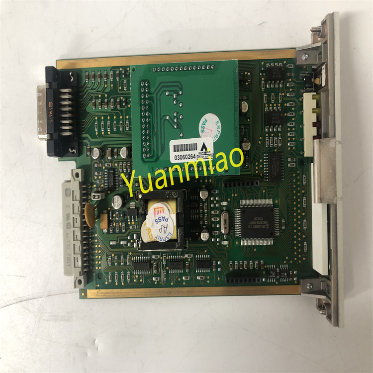
GE IS200VCRCH1BBC
GE IS200VCRCH1BBC is a core module of the high-end digital excitation regulator launched by General Electric (GE), belonging to the Mark VIe series excitation control system. It is specifically designed for excitation regulation scenarios of power generation equipment such as large synchronous generators, hydro-generators, and turbo-generators. It is widely used in industries with strict requirements for excitation control accuracy and stability of power generation equipment, including thermal power plants, hydropower plants, nuclear power plants, and industrial self-owned power stations.
Adopting a multi-core digital signal processing architecture, this module integrates core functions such as excitation current regulation, voltage closed-loop control, power factor adjustment, fault diagnosis, and multi-protocol communication. It can seamlessly connect to GE Mark VIe series controllers, excitation power units (e.g., thyristor rectifier bridges), and upper-level monitoring systems, providing a full-process high-precision excitation control solution for generators—covering voltage acquisition, logical operation, and excitation output. This ensures stable generator terminal voltage, optimized power factor, and safe excitation support under grid faults.
As the core computing unit of the Mark VIe series excitation control system, the IS200VCRCH1BBC features excellent computing performance and system compatibility. Equipped with a dual-core high-performance DSP processor, it supports multi-task parallel processing with an excitation regulation response time of ≤10ms. It can seamlessly interface with various detection components such as generator potential transformers (PT), current transformers (CT), and speed sensors, adapting to the excitation control needs of generators with different capacities (100MW-1000MW). Relying on enhanced redundancy design, wide-range environmental adaptability, and intelligent operation and maintenance functions, it can operate continuously and stably under harsh working conditions such as high temperature, high humidity, strong electromagnetic interference, and vibration. It provides reliable excitation control support for scenarios like generator grid-connected power generation, load fluctuation adjustment, and grid voltage support, helping power generation equipment improve power generation quality, operating efficiency, and grid adaptability.
High-Precision Excitation Closed-Loop ControlEquipped with a dual-core TI C6748 high-performance DSP processor with a main frequency of 1GHz, it adopts an advanced PID + adaptive control algorithm to realize triple closed-loop control of generator terminal voltage, excitation current, and power factor. The terminal voltage control accuracy reaches ±0.2% of the rated voltage, with a voltage adjustment range of 80%-110% of the rated voltage, supporting online smooth adjustment of the voltage set value. The voltage fluctuation range is ≤±1% of the rated voltage when the load fluctuates. The excitation current control accuracy is ≤±1% of the rated excitation current, enabling constant excitation current output. The power factor control accuracy is ≤±0.01, supporting bidirectional switching control between the power factor set value and the reactive power set value. It is equipped with excitation limitation functions, including over-excitation limitation, under-excitation limitation, and excitation current quick-break limitation. The limitation values can be flexibly configured through parameters to ensure the safe operation of the excitation system.
Multi-Mode Operation and Flexible AdaptationIt has four core operating modes: Automatic Voltage Regulation (AVR), Manual Voltage Regulation (MVR), Constant Power Factor Regulation (PFCR), and Constant Reactive Power Regulation (QCR). Undisturbed mode switching can be achieved through three methods: panel buttons, upper-level system commands, or automatic fault switching. The excitation current fluctuation during switching is ≤±3% of the rated value. It supports no-load excitation regulation before grid connection and load excitation regulation after grid connection. Before grid connection, it maintains stable generator terminal voltage through voltage closed-loop control; after grid connection, it automatically adjusts excitation according to grid requirements to achieve reasonable distribution of reactive power. It is compatible with different types of generators such as hydro-generators, turbo-generators, and gas generators. Optimized control parameters are preset according to the characteristics of different generators, and parameters can be further fine-tuned through configuration software to match equipment characteristics. It supports linkage with automatic synchronization devices to realize coordinated excitation regulation during the automatic grid connection of generators.
Redundancy Fault Tolerance and High-Reliability DesignIt adopts a 1oo2 (1-out-of-2) redundant hardware architecture, with built-in dual independent DSP core computing units, dual redundant power interfaces, dual communication interfaces, and dual storage units. The dual computing units synchronously execute the excitation control program and conduct real-time cross-verification of computing results and operating status. Under normal working conditions, the dual units work in parallel and output control commands after passing data consistency verification. When one unit experiences hardware failure or computing abnormality, the built-in diagnostic circuit identifies the fault and isolates the faulty unit within 5ms, and the other unit seamlessly takes over all control functions without interruption of excitation regulation. The redundant storage units adopt a combined Flash + EEPROM design, with dual storage of programs and configuration data, supporting automatic data recovery after faults to ensure the integrity of system configuration and operating data. The module uses a full-metal shielded enclosure with an IP20 protection rating. The internal circuit adopts photoelectric isolation (isolation voltage ≥2.5kV AC) and EMC filtering design, complying with the IEC 61000-4 series electromagnetic compatibility standards and resisting strong electromagnetic interference.
Comprehensive Fault Diagnosis and Safety ProtectionA three-level intelligent diagnosis system (module-level, channel-level, and system-level) is built, with a diagnosis coverage rate of 99.9%. Module-level diagnosis monitors the operating status of the dual DSPs, power supply voltage, health status of storage units, and connectivity of communication links in real time. Channel-level diagnosis monitors the signal amplitude, line on/off status, and drift trend of voltage acquisition channels, current acquisition channels, and excitation output channels. System-level diagnosis monitors key parameters such as the status of the excitation power unit, generator speed, and grid frequency. Diagnostic information is displayed through the front-panel LED indicators and LCD screen, supporting query of detailed information such as fault codes, fault locations, and fault times. At the same time, it is uploaded to the operation and maintenance platform through the communication interface, supporting storage and traceability of 1000 fault history records. Fault codes are accompanied by troubleshooting guides and maintenance suggestions. It has grid fault ride-through capability; when the grid experiences voltage sag or surge, it automatically activates the under-excitation or over-excitation limitation function to maintain stable generator excitation and avoid grid disconnection.
Rich Communication and Interaction FunctionsIt is equipped with complete communication interfaces, including 2 standard redundant Ethernet interfaces (supporting EtherNet/IP and Modbus TCP protocols), 2 RS485 communication interfaces (supporting Modbus RTU protocol), and 1 GE-specific Genius bus interface. It can achieve high-speed data interaction with Mark VIe controllers, SCADA systems, HMI (Human-Machine Interface), and third-party equipment. It supports uploading of more than 30 operating parameters (such as generator terminal voltage, excitation current, power factor, and reactive power) to the upper-level system, with a configurable upload cycle (1ms-100ms). At the same time, it receives control signals from the upper-level system, such as voltage set values, power factor commands, and mode switching commands. The maximum data transmission rate reaches 1Gbps, with a transmission delay of ≤5ms. It has dual local and remote operation functions: locally, parameter setting, status monitoring, and fault query are realized through 6 function buttons and a 3.5-inch color LCD screen; remotely, full-function operation is realized through the communication interface, supporting remote parameter modification and program upgrade.
Convenient Configuration and Operation & Maintenance ManagementIt supports in-depth parameter configuration through GE-specific configuration software (ToolboxST). The software provides a graphical programming interface, enabling intuitive construction of control logic, configuration of PID parameters, setting of protection thresholds, and definition of communication parameters. It has a built-in rich library of excitation control function blocks (such as voltage adjustment blocks, excitation limitation blocks, and fault diagnosis blocks) and supports online modification and downloading of control logic. It is equipped with an online auto-tuning function; by executing the auto-tuning process, it automatically identifies the dynamic characteristics of the generator excitation system (such as the time constant of the excitation winding and synchronous reactance) and optimizes PID parameters, simplifying the debugging process. It supports online program upgrade; firmware upgrade can be completed through the communication interface, and during the upgrade process, it automatically switches to the redundant unit for operation to ensure no interruption of excitation regulation. It is equipped with a predictive maintenance function; by analyzing the operating parameters and aging trends of core components, it predicts potential faults 3-6 months in advance, reducing unplanned downtime.
The working principle of the GE IS200VCRCH1BBC excitation regulation module revolves around six core links: "redundant power supply - signal acquisition - command processing - closed-loop calculation - excitation output - diagnostic protection". Through dual-core redundant calculation and a closed-loop control mechanism, it achieves high-precision excitation regulation and reliable safety assurance for generators. The specific working principle is as follows:
After two independent DC 24V power supplies are connected to the module through redundant power supply interfaces, they first pass through an EMC filter and a surge suppressor to filter out high-frequency interference and surge impact signals in the power grid, ensuring the stability of the input power supply. Then, they enter two independent intelligent power management units. Each unit is equipped with a high-precision voltage sensor, current sensor, and temperature sensor, which monitor the input voltage, output current, and module temperature in real time and upload the data to the dual DSPs. The main DSP comprehensively determines the main and standby power supplies based on parameters such as voltage stability (fluctuation ≤±5%), current load rate (≤60%), and temperature (≤40℃). By default, the optimal power supply is selected as the main power supply, and the other is in a hot standby state, with electrical isolation achieved through magnetic beads and isolation diodes. When the main power supply voltage is lower than 20.4V, higher than 27.6V, or the load rate is ≥90%, the power switching circuit quickly switches to the standby power supply within 5ms. During the switching process, a super capacitor maintains power supply to the core circuit (duration ≥100ms) to ensure no power supply interruption. The stabilized power supply is converted by the DC-DC conversion unit into multiple precise voltage outputs (3.3V for DSP core, 5V for interface circuit, 12V for drive circuit, etc.), which are supplied to each functional unit after LC filtering. The output ripple is ≤5mV to ensure stable circuit operation.
The generator terminal voltage is stepped down by a potential transformer (PT) and then connected to the module through an analog input channel; the excitation current is converted by a current transformer (CT) and then connected to the module through another group of analog input channels; auxiliary signals such as generator speed, grid frequency, and power factor are also connected simultaneously. All analog signals first enter the signal conditioning unit, where they undergo differential amplification, noise filtering (low-pass filtering), and photoelectric isolation to eliminate electromagnetic interference and common-mode noise during transmission. Then, they are converted into digital signals by a 16-bit high-precision ADC converter with a sampling frequency of 1kHz, ensuring the real-time and accuracy of signal acquisition. Digital signals (such as synchronization signals and fault signals) are directly input to the DSP after photoelectric isolation and level conversion to avoid interference of external signals on the core circuit. The processed digital signals are stored in a dual-port RAM, and the dual DSPs read the signal data synchronously to provide accurate input data support for closed-loop calculation.
The module receives control commands (including voltage set values, power factor commands, and mode switching commands) through the local panel or communication interface. Local commands are input through panel buttons, converted into digital signals by the key scanning circuit, and then transmitted to the dual DSPs; remote commands are received through the communication interface, decoded into digital control signals by the protocol parsing unit, and then transmitted to the dual DSPs. The dual DSPs perform priority judgment and validity verification on the commands. Safety commands such as emergency shutdown and excitation limitation have the highest priority, while voltage set values and power factor commands need to be verified to ensure they are within the allowable range (e.g., voltage set value: 80%-110% of the rated value). According to the mode switching command, the dual DSPs synchronously switch to the corresponding operating mode (AVR/MVR, etc.) and call the corresponding control algorithm and parameters. In the case of automatic fault switching mode, the fault type must be determined first to ensure switching to a safe mode. After command processing is completed, target reference values (such as target voltage and target excitation current) are generated and transmitted to the closed-loop calculation unit.
The dual DSPs synchronously execute the triple closed-loop control algorithm. Taking the Automatic Voltage Regulation (AVR) mode as an example: ① Voltage outer loop: Compare the target voltage with the actual measured terminal voltage, calculate the voltage deviation, perform calculation through the PID + adaptive control algorithm, and output the excitation current reference command. The algorithm integrates a voltage smooth adjustment strategy to avoid excitation impact caused by sudden changes in the set value. ② Current middle loop: Compare the excitation current reference command with the actual measured excitation current, calculate the current deviation, perform calculation through the PID algorithm, and output the power factor correction reference command. ③ Power factor inner loop: Compare the power factor correction reference command with the actual measured power factor, calculate the power factor deviation, perform calculation through the PID algorithm again, and output the excitation control command. After the dual DSPs complete the calculation, they cross-verify the calculation results. If the results are consistent and meet the excitation limitation requirements, the final control command is generated; if the results are inconsistent, a self-inspection program is immediately activated to locate the faulty DSP, isolate the faulty unit, and the normal DSP takes over the calculation, while triggering a redundancy fault alarm. When multiple units operate in parallel, they receive excitation data of other generators through the communication interface, execute the reactive power distribution algorithm, and adjust their own control commands to achieve grid reactive power balance.
![]()