Description
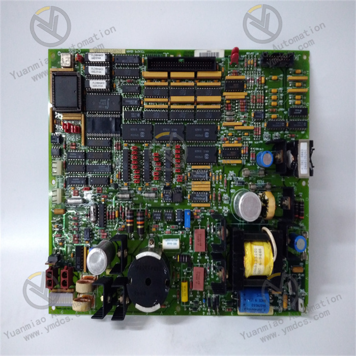
DS215SDCCG1AZZ01B
Functional Features
- Multi-Processor Collaborative Operation
Includes a Drive Control Processor (DCP), Motor Control Processor (MCP), and Co-Motor Processor (CMP). - The DCP controls the driver, supports digital and analog I/O functions, and manages the user interface.
- The MCP handles high-intensity mathematical operations related to motor control, such as current regulation.
- When the MCP's processing capacity is insufficient, the CMP takes over to handle complex motor control algorithms.
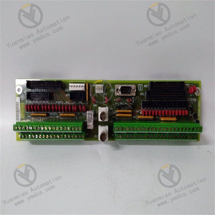
- Abundant Signal Interfaces
Equipped with 8 connectors (1PL, 2PL, 3PL, 6PL, 7PL, 8PL, 9PL, and 11PL) to connect with other circuit boards, transmit and receive signals, and provide various AC and DC motor drive configurations for the driver system. - Convenient Fault Diagnosis
Ten diagnostic LEDs on the board display fault codes in binary or Binary Coded Decimal (BCD) format, enabling users to quickly locate issues.
Technical Parameters
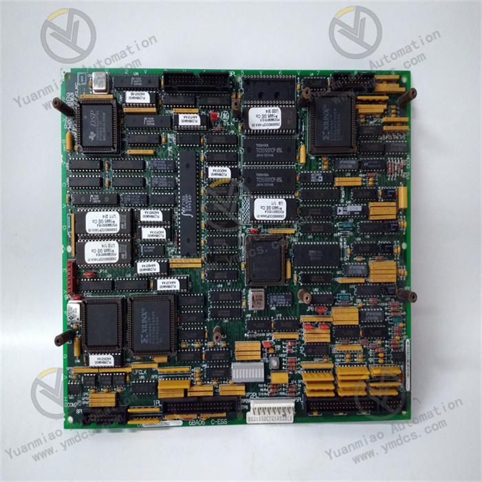
- Microcontrollers
- DCP: Based on the 80C186 microcontroller.
- MCP: Based on the 80C196 microcontroller.
- CMP: Adopts the TMS320C25 digital signal processor.
- Memory
Integrates dual-port RAM, with storage provided by 5 onboard memory chips. - Software Suite
Uses the ST2000 software suite.
Working Principle
- Drive Control Processor (DCP)
Based on the 80C186 microcontroller, it supports digital and analog input/output (I/O) and features built-in peripheral functions such as address decoding, wait state generation, interrupt control, timing/counting, and Direct Memory Access (DMA). DCP software manages the user interface, external regulation loops (e.g., speed and position control), and system-level operations, performing preliminary processing and allocation of various input signals to coordinate overall system operation. - Motor Control Processor (MCP)
Centered on the 80C196 microcontroller, it provides high-speed I/O, traditional digital I/O, analog I/O, timer/counter, and watchdog timer functions. The MCP primarily handles internal loops related to motor control (e.g., current regulators) and executes motor-specific operations such as DC phase control and AC motion control, ensuring the motor runs as expected through precise control of motor-related parameters. - Co-Motor Processor (CMP)
Using the TMS320C25 digital signal processor, the CMP takes over when the MCP cannot handle complex motor control algorithms. It interfaces with dual-port RAM and EPROM, mainly processing complex motor control algorithms. Through its powerful computing capability, it addresses control tasks requiring high precision and complex calculations to meet the precise control needs of the turbine drive system under different operating conditions. - Signal Interaction and Processing
The control card connects with other boards and external devices via 8 connectors (1PL, 2PL, 3PL, 6PL, 7PL, 8PL, 9PL, and 11PL). It receives signals from sensors or other control units, processes them through collaborative operations of the three processors, and outputs control signals to corresponding actuators to achieve precise control of turbine drive components. Meanwhile, the 10 diagnostic LEDs on the board display fault codes in binary or BCD format, facilitating fault troubleshooting and system maintenance for users.