Description
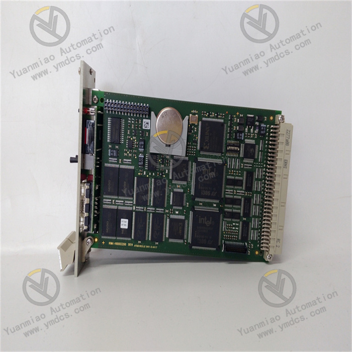
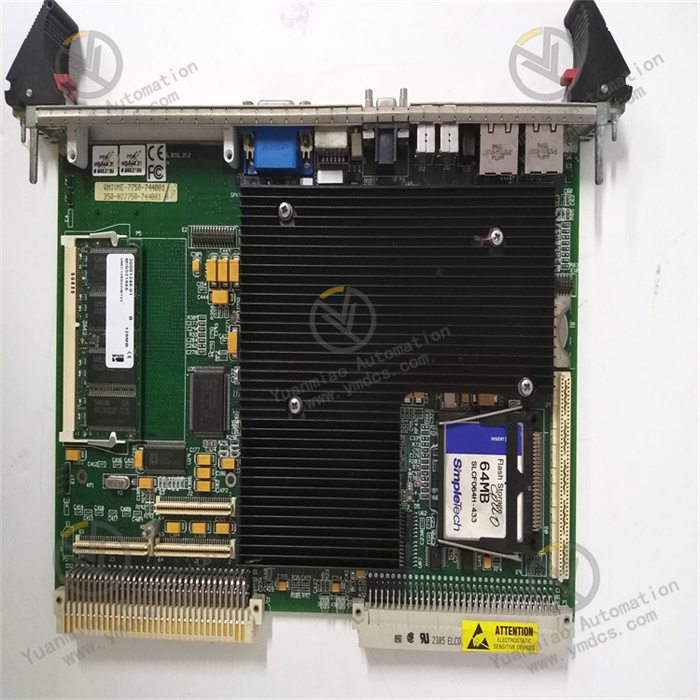
VMIVME-7750-540
I. Overview
The Abaco Systems VMIVME-7750-540 is a 6U single-slot VMEbus Single-Board Computer (SBC) playing a key role in industrial control, communication, data processing, and other fields. Since its launch, it has won wide recognition in the industry for its excellent performance and reliable quality. Although it entered the Restricted Production Phase (RPP) since February 5, 2009, it still holds a certain market share due to its unique advantages. Based on the mature VME (VersaModule Eurocard) bus architecture, it adopts a compact single-slot, passive-cooled Eurocard form factor, featuring high stability and expandability to excellently meet the rigorous requirements of different industries for high-performance computing and complex data processing.
II. Functional Features
(1) High-Performance Processor Core
Equipped with an Intel Pentium III processor running at up to 933 MHz (some models support up to 1.26 GHz), the processor has 32-bit addressing and a 64-bit data bus. Its superscalar architecture allows executing three instructions per clock cycle. Meanwhile, the dynamic branch prediction unit, independent instruction and data caches, and MMX™ technology significantly enhance the overall processor performance. Additionally, the 256 KB (512 KB for 1.26 GHz models) Advanced Transfer Cache (on-die full-speed L2 cache) implemented via a dual independent bus architecture brings high bandwidth and performance to the processor, operating at the same clock frequency as the processor to greatly optimize data processing speed.
(2) Sufficient Memory Configuration
Featuring up to 512 MB of PC133 SDRAM, realized via a single 144-pin SDRAM Small Outline Dual In-line Memory Module (SODIMM). This memory configuration provides ample space for system operation and temporary data storage, ensuring the system remains efficient and stable during multi-task parallel processing or large-scale data handling, avoiding lag or data loss caused by insufficient memory. Moreover, the DRAM is connected to the VMEbus via dual ports, effectively improving data transmission efficiency.
(3) Rich Graphics Display Capability
With a built-in AGP graphics adapter based on the 815E chipset, it provides powerful Super VGA (SVGA) support, equipped with a 4 MB external synchronous DRAM cache and a 64-bit high-bandwidth data interface. It supports screen resolutions up to 1600×1200×256 colors (single-view mode), capable of presenting high-resolution graphics and multimedia-quality video to meet application scenarios with high graphics display requirements, such as industrial visual monitoring and complex data visualization.
(4) Diverse Network Connectivity
Supporting Ethernet LAN, it is equipped with two Intel Ethernet controllers (one is 82559, and the other is integrated into the Intel chipset ICH 2), providing 10BaseT and 100BaseTX network connection options via two RJ45 connectors. Meanwhile, using Lanworks Technologies' Bootware® technology, it supports remote Ethernet boot through network protocols such as Netware, TCP/IP, or RPL, facilitating device deployment and management in remote environments and enhancing system maintainability and flexibility.
(5) Convenient Storage and Expansion Functions
Supporting IDE drives to provide basic data storage guarantee. It has a PMC expansion site, allowing users to flexibly insert PMC modules with various functions (e.g., adding specific communication interfaces, data acquisition function modules) according to actual application needs, greatly enhancing the device's versatility and adaptability to better meet diverse functional expansion requirements in different application scenarios. In addition, the system and video BIOS are stored in reprogrammable flash memory for easy upgrading and maintenance.
III. Working Principle
(1) System Startup Process
When the VMIVME-7750-540 is connected to the VMEbus system and powered on, the onboard power management circuit first converts, stabilizes, and filters the input power to provide stable and adaptive working voltages for internal components (e.g., processor, memory, various interface circuits). Subsequently, the processor reads startup code from the BIOS in the reprogrammable flash memory and loads the operating system kernel and related drivers. During this process, the BIOS comprehensively detects and configures the system's hardware resources, including memory initialization, timer setup, I/O interface initialization, etc., to ensure all device parts are in normal working condition, preparing for subsequent data processing and task execution. After initialization, according to the preset boot order, if network boot is selected, the device will obtain boot files from a remote server via the Ethernet controller based on Bootware® technology and following corresponding network protocols (e.g., Netware, TCP/IP, or RPL) to complete system startup; if booting from a local storage device (such as an IDE drive), it reads the operating system and related data locally to start the system.
(2) Data Processing Mechanism
In the data processing process, when the system receives external data processing task instructions, the Pentium III processor parses and computes the tasks according to preset programs and algorithms. The processor uses its powerful computing capability to quickly handle complex logical operations and data manipulations. For example, in industrial automation control scenarios, it analyzes massive real-time data collected by sensors, judges the operating status of production equipment, and generates corresponding control instructions based on the analysis. During computation, the processor frequently interacts with the onboard SDRAM, reading required data from memory and timely storing operation results back into memory. Meanwhile, with the processor's dynamic branch prediction unit, it pre-judges the program execution path in advance, reducing instruction execution waiting time and improving computing efficiency. For data requiring graphics processing, such as video image data in industrial monitoring, it is transmitted to the built-in AGP graphics adapter, which uses its 4 MB DRAM cache and high-bandwidth data interface for efficient processing, ultimately outputting high-quality graphics display results.
(3) Data Transmission Principle
The device transmits data with external devices via the VMEbus. When communicating with other VMEbus devices, data is orderly transmitted between devices through address lines, data lines, and control lines under the VMEbus protocol. For the onboard Ethernet controller, during network data transmission, it follows the Ethernet protocol to encapsulate and decapsulate data. For example, when the device needs to send locally processed data to other devices in the network, the data is first transmitted to the Ethernet controller, which encapsulates the data into Ethernet frames according to the 10BaseT or 100BaseTX standards and sends them to the network via the RJ45 interface; when receiving data, the process is reversed—the Ethernet controller receives Ethernet frames from the network, decapsulates them, and transmits the data to the processor or memory for subsequent processing. If data transmission is performed via an extended PMC module, the PMC module converts data into a format suitable for VMEbus transmission based on its functional characteristics and interface protocol, then sends and receives data on the VMEbus. The entire data transmission process strictly follows relevant protocols to ensure data transmission accuracy and efficiency, enabling stable and reliable data communication between the device and the external environment.
IV. Operation Guide
(1) Pre-installation Preparations
- Compatibility Verification: Before installation, carefully verify the detailed specifications of the target VMEbus system. Focus on key information such as VMEbus slot type, quantity, electrical characteristics, and available power to ensure full compatibility with the VMIVME-7750-540. Incompatible systems may cause installation failure or device damage, making compatibility confirmation a crucial step before installation.
- Tool Preparation: Prepare necessary installation tools, such as anti-static wristbands and screwdrivers of suitable sizes. Wear an anti-static wristband during operation to prevent static electricity from damaging sensitive internal electronic components, ensuring installation safety.
(2) Module Installation
- Chassis Opening Operation: Carefully open the VMEbus system chassis and locate a suitable 6U single-slot position inside for installing the VMIVME-7750-540 module.
- Module Insertion Steps: Hold the VMIVME-7750-540 module, precisely align its bottom interface with the VMEbus slot, maintain verticality, and insert it smoothly and slowly into the slot. Avoid excessive force to prevent pin bending or damage, ensuring the module is fully seated and fixed.
- Module Fixing Key Points: Use a screwdriver to tighten the fixing screws on both sides of the module one by one, ensuring the module is firmly installed in the chassis without shaking, providing a solid physical guarantee for stable device operation.
(3) Device Connection
- Storage Device Connection (Optional): To connect storage devices such as IDE drives, prepare corresponding data and power cables. Connect one end of the data cable to the device's IDE interface and the other end to the storage device; meanwhile, correctly connect the power cable to the storage device to enable data storage and reading between the device and the storage device.
- Network Device Connection: Connect the device's RJ45 interface to a network switch or other network devices with Ethernet cables, and configure the device's network parameters (such as IP address, subnet mask, gateway) according to the actual network environment to ensure the device can normally access the network for data transmission and sharing.
- Expansion Module Connection (if any): For PMC module expansion, insert the selected PMC module into the PMC expansion site in the correct orientation and manner, ensuring it is firmly fixed. After insertion, according to the PMC module's functions and requirements, corresponding driver installation and configuration operations may be required to make it work normally.
(4) System Startup and Operation
- System Startup Process: After completing all device connections, close the VMEbus system chassis and power on the system. Observe the device's indicator lights during startup; normally, the lights will turn on or flash in a specific sequence, indicating the device is performing self-checking and other startup processes. If the indicators show abnormalities, refer to the device manual or contact technical support for troubleshooting.
- System Login and Operation: After startup, enter the correct username and password in the corresponding login interface based on the installed operating system. Upon successful login, use the device's functions for data processing, control operations, etc., via the OS or related applications—e.g., remotely monitoring and controlling production equipment through dedicated control software in industrial automation, or starting a data analysis program to process and analyze collected data in data processing scenarios.
(5) Common Fault Troubleshooting
- Device Fails to Start: Check power connections for stability and confirm normal external power supply; inspect indicator light status. If lights are off or abnormal, the internal power module may be faulty, requiring professional maintenance. Meanwhile, verify that the boot device (e.g., IDE drive, network boot configuration) is properly connected and has intact data, as boot device issues may prevent normal system startup.
- Abnormal Network Connection: If the device cannot connect to the network normally, check Ethernet cables for damage and try reinserting or replacing them; confirm network parameter configuration is correct and test network connectivity via commands like ping. If the problem persists, check whether the Ethernet controller driver is correctly installed and up to date (download updates from the device manufacturer's official website).
- Abnormal Expansion Module Function (if applicable): If a inserted PMC module fails to function, check for correct installation and secure fixing; confirm module-device compatibility and whether specific drivers need installation or configuration. If issues persist, contact the module supplier or Abaco Systems technical support for assistance.