Description
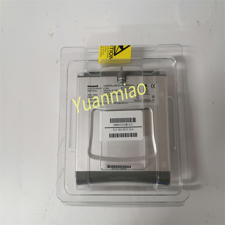
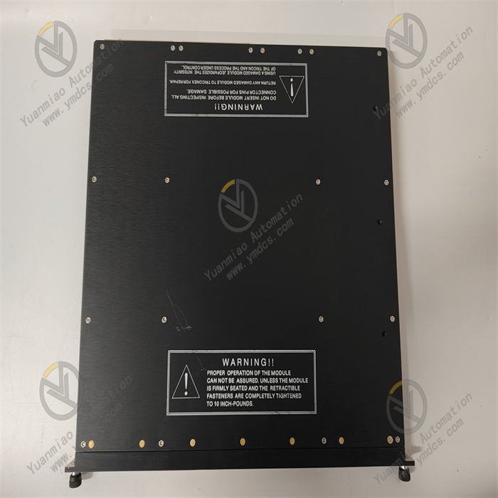
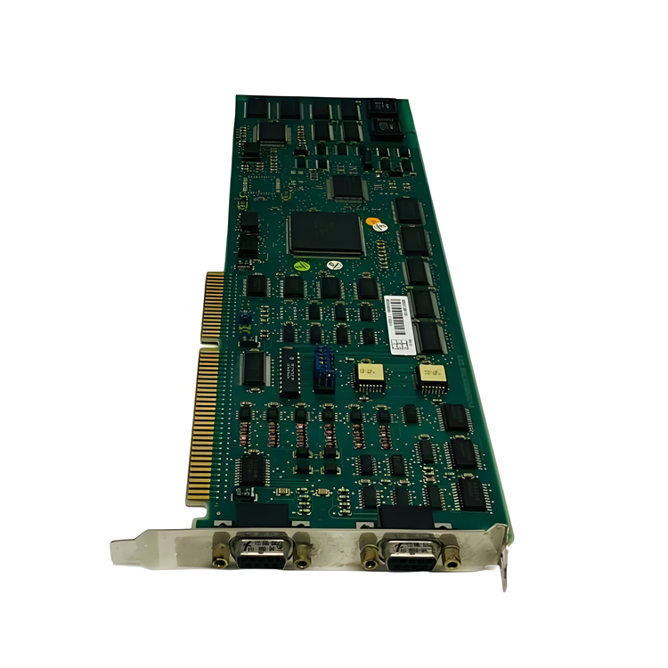
ABB CI526 3BSE006085R1
Basic Information
Product Type: Communication Interface Module
Country of Origin: Sweden
Product Purpose: Used to connect different systems or devices to enable data transmission and communication. For example, in industrial automation control systems, it connects controllers with other intelligent devices or systems, allowing them to communicate and collaborate with each other.
Technical Parameters
- Operating Voltage: 24V
- Output Frequency: 10/100Mbps
- Processing Speed: 50MHz
- I/O Points: 3
- Structure: Modular
- Instruction Processor: Hard PLC
- Controller Configuration: Configurable using the 800xA Control Builder
- Communication Connections: Hardware based on communication connection standards, supporting communication protocols such as Ethernet and PROFIBUS DP, and using a pair of BC810 segmented CEX buses.
Functional Features
- Interface Conversion: As a coupler from ISA to AF100, it enables conversion between different bus or interface standards, allowing devices using the ISA bus to communicate with those using the AF100 bus and solving compatibility issues between devices with different interfaces.
- Multiple Communication Protocols Supported: Supports multiple communication protocols such as Ethernet and PROFIBUS DP, facilitating connection and communication with different types of devices or systems. It has strong versatility and flexibility, adapting to various industrial communication scenarios.
- Processing Capability: With a processing speed of 50MHz and a hard PLC instruction processor, it can quickly process communication data, ensuring the timeliness and accuracy of data transmission to meet the real-time requirements of industrial automation systems.
How to Install and Configure the ABB CI526 3BSE006085R1 Module?
I. Installation Steps
- Physical Installation
- Safety Preparation:
- Power off the module and related devices, and wear an anti-static wrist strap to avoid electrostatic damage to components.
- Ensure the installation environment meets requirements (Temperature: -25°C~+70°C, Humidity: 5%~95% non-condensing).
- Mechanical Fixation:
- Rail Mounting: Use a standard DIN rail, align the module's 卡扣 (clips) with the rail and press to ensure a secure lock.
- Screw Fixation (Optional): For additional reinforcement, use M4 screws through the mounting holes on both sides of the module.
- Power Connection:
- Use a 24V DC power supply (allowing ±10% voltage fluctuation) and connect it to the module's power terminals (pay attention to positive and negative polarities).
- It is recommended to use a redundant power supply (e.g., two 24V DC supplies) to improve reliability; some models support dual power inputs.
- Communication Cable Connection:
- Ethernet Interface: Use CAT5e/6 network cables to connect to switches or controllers, ensuring the RJ45 interface is tightly plugged.
- PROFIBUS DP Interface: Use shielded twisted-pair cables, connect according to RS-485 standards (corresponding to A/B wires), and terminate the end node with a 120Ω termination resistor.
- System Integration
- Backplane Bus Connection (if applicable):
- Insert the module into the backplane bus slot of the control system, ensuring the gold fingers make full contact with the slot.
- Some models require special connectors (e.g., ABB's BC810 bus connector) to enable communication between modules.
- Grounding:
- Connect the module's grounding terminal to the control cabinet's grounding bar, with a grounding resistance of less than 4Ω.
- The shielding layer of communication cables must be grounded at a single point (usually on the control cabinet side) to avoid ground loop interference.
II. Configuration Process
- Hardware Configuration (Physical Address Setup)
- DIP Switch Setup (if available):
- Set communication parameters (e.g., slave address, baud rate) via DIP switches on the module's side.
- Example: To set the PROFIBUS DP slave address to 2, toggle the corresponding switch to the "ON" position.
- Jumper Configuration (if available):
- Some models require jumpers to select operating modes (e.g., RS-232/RS-485 mode switching).
- Use special jumper caps to connect corresponding pins as instructed in the manual.
- Software Configuration (Programming Tool Setup)
- Programming Software Preparation:
- Install ABB official software (e.g., Control Builder M or 800xA Control Builder).
- Ensure the software version is compatible with the module's firmware (refer to ABB technical documentation).
- Create a Project and Add the Module:
- Create a new project in the software and select the correct controller model (e.g., AC 800M).
- In the hardware configuration interface, add the CI526 module according to the actual physical location (Path: I/O Configuration → Communication Modules → CI526).
- Parameter Setup:
- Communication Protocol: Select Ethernet, PROFIBUS DP, or other protocols.
- Baud Rate/Speed: Match the counterpart device (e.g., PROFIBUS DP can select 9.6kbps~12Mbps).
- Slave Address: Set a unique ID (e.g., PROFIBUS DP address range: 1~126).
- Data Format: Configure data bits, stop bits, and parity (e.g., 8N1 indicates 8 data bits, no parity, 1 stop bit).
- Function Block Configuration:
- Invoke communication function blocks (e.g., Modbus TCP Master/Slave) in the programming environment.
- Configure read/write addresses, data length, and refresh cycle (e.g., read registers every 100ms).
- Network Topology Configuration
- PROFIBUS DP Network:
- Import ABB's GSD file (e.g., CI526.gsd) into the software to define the module's I/O address mapping.
- Set bus parameters (e.g., transmission rate, maximum number of stations) to ensure network load does not exceed 30%.
- Ethernet Network:
- Configure IP address, subnet mask, and gateway (e.g., IP: 192.168.1.100, Mask: 255.255.255.0).
- Enable necessary protocols (e.g., Ethernet/IP, Modbus TCP) and set communication timeout parameters.
III. Debugging and Verification
- Power Test:
- Apply power and observe the module's indicator lights:
- PWR Light: Constant on indicates normal power supply; flashing or off requires checking the power circuit.
- COM Light: Should flash during communication; constant on or off may indicate parameter errors or link interruptions.
- Communication Test:
- Use diagnostic tools (e.g., ABB's Commissioning Tool) to check the module's status.
- Send test data (e.g., read holding registers) to verify normal data transmission and reception.
- Troubleshooting:
- If communication fails, check:
- Whether cables are loose or reversed (e.g., RS-485 A/B wires).
- Whether parameter settings match the counterpart device (baud rate, address, etc.).
- Whether network load is too high (monitored via a bus analyzer).