Description
GE DS200TCEAG1BNE
GE DS200TCEAG1BNE is a core component of the Speedtronic Mark V gas turbine control system, functioning as an Emergency Overspeed Board. It is also compatible with relevant industrial automation control systems of the TC2000 series. Designed specifically for the safe operation of gas turbines and steam turbines, it serves as a critical safety hub for unit overspeed protection. It operates independently of the main control system, providing the final safeguard for safe unit shutdown under extreme operating conditions.
1. Basic Information & Functions
Part Number: DS200TCEAG1BNEProduct Type: Emergency Overspeed Board (Turbine Control Electronics, TCE). It belongs to the GE Mark V / Speedtronic DS200 series and is the B enhanced revised version of Group G1 hardware, with overall performance upgrades compared to the A version.Brand: GE (General Electric)
- Overspeed Monitoring and Tripping: Real-time monitoring of gas turbine / steam turbine speed. When the speed exceeds the preset threshold, it immediately triggers hardwired trip output to drive emergency unit shutdown with a response time of less than 8ms, preventing unit damage.
- Flame Detection and Interlock: Receives pulse signals from flame detectors to judge combustion status, supports shutdown interlock on flameout, and achieves full-condition safety coverage.
- Signal Acquisition and Processing: Collects field signals such as speed pulses and flame detection signals. After isolation, filtering and waveform shaping, it performs frequency calculation and logic judgment to ensure stable and reliable signals.
- Fault Diagnosis and Reporting: Continuously monitors its own status and related loop conditions. It automatically uploads fault codes upon abnormality and enables fast faulty channel positioning for easy maintenance.
- Data Transmission and Coordination: Communicates with the Mark V P1 protection core via the IONET network, uploading speed, flame and fault data while receiving main control commands to realize coordinated operation between protection logic and the main control system.
2. Technical Specifications
| Parameter Item | Specification Details |
|---|---|
| Part Number | DS200TCEAG1BNE |
| Series | GE Mark V / Speedtronic / DS200, TC2000 Series |
| Hardware Group / Revision | Group G1, Version B (Function Enhanced Edition) |
| Processor | Intel 80196 16-bit microprocessor (independent operation, not affected by main control system) |
| Signal Input | 4-channel speed pulse input (HP shaft / LP shaft); 2-channel flame detection pulse input |
| Trip Output | 4 independent hardwired trip outputs (24VDC / dry contact, directly driving shutdown loop) |
| Communication Interface | IONET network (communication with P1 protection core); 2 bayonet connectors |
| Configuration Method | 30 jumpers (J1–J30) for IONET address, trip frequency, pulse selection, shaft configuration, etc. |
| Protection Mechanism | 3 built-in fuses, surge suppression, overvoltage / overcurrent protection, EMI/RFI filtering |
| Isolation Withstand Voltage | ≥2500VAC (field side to protection core side) |
| Operating Temperature | -40°C ~ +85°C (wide temperature range for harsh industrial environments) |
| Relative Humidity | 5%–95% RH (non-condensing) |
| Physical Dimensions | Approx. 168mm × 150mm × 55mm |
| Weight | Approx. 0.91kg (2.0lbs) |
| Mounting Position | Dedicated slot in the P1 protection core area of Mark V control cabinet |
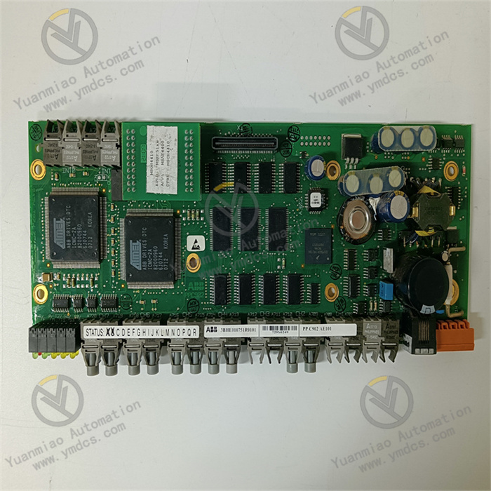
3. Hardware Design & Structural Features
- Interface Area: Equipped with 2 bayonet connectors for connecting speed / flame sensors and trip loops, featuring firm connection and vibration resistance to adapt to complex industrial site environments.
- Jumper Area: 30 jumpers (J1–J30) are centrally arranged for quick configuration of IONET address, trip frequency, pulse selection and other parameters to match different unit requirements.
- Protection Component Area: Built-in 3 fuses with integrated surge suppression and EMI/RFI filtering circuits, providing centralized protection against overvoltage, overcurrent and electromagnetic interference for core board components.
4. Working Principle & Signal Flow
- Signal Access: Sine wave / square wave pulse signals from field speed sensors (magnetoelectric / photoelectric) and pulse signals from flame detectors are connected to corresponding channel terminals via bayonet connectors.
- Signal Processing: Input signals undergo EMI/RFI filtering, high-voltage isolation and waveform shaping, then are sent to the Intel 80196 16-bit microprocessor to eliminate on-site electromagnetic interference and voltage fluctuation, ensuring clean and accurate signals.
- Logic Judgment: The processor calculates the frequency of speed pulses in real time and converts it into actual rotational speed (RPM) for comparison with preset trip thresholds. It also monitors flame signal status to identify normal combustion and judge abnormal conditions such as overspeed and flameout.
- Fault Detection & Reporting: Continuously monitors speed pulses, flame signals, processor status and trip loops. Once an abnormality occurs, an alarm is triggered immediately and fault codes are uploaded to the P1 protection core for rapid troubleshooting by maintenance personnel.
- Interlock Action: When dangerous conditions such as overspeed or flameout are detected, 4 independent hardwired trip outputs are activated instantly to directly drive unit shutdown solenoid valves, realizing millisecond-level emergency shutdown and avoiding unit damage. Meanwhile, operation status is uploaded to the main control system via the IONET network.
5. Key Features & Advantages
- Independent Protection & High Reliability: Adopts an independent processor and standalone operating architecture, completely unaffected by main control system faults. It can still execute overspeed protection and emergency shutdown logic even if the main control system fails, acting as the final safety line of defense for the unit.
- Version B Upgrade & Better Performance: Compared with Version A, Revision B achieves comprehensive upgrades in trip drive current (50% increase), fault diagnosis accuracy (added channel-level fault positioning), IONET communication rate (upgraded from 1Mbps to 2Mbps) and anti-interference performance, adapting to unit control scenarios with higher safety integrity levels.
- Precise Monitoring & Fast Response: Speed monitoring accuracy reaches ±0.5RPM with overspeed trip response time less than 8ms. Dual-shaft redundant monitoring and multi-channel signal acquisition effectively prevent false tripping and missing protection, ensuring stable unit operation.
- Convenient Maintenance & High Flexibility: 30 jumpers allow flexible parameter configuration to adapt to units with different rated speeds. Faulty channels can be quickly located, supporting rapid repair and refurbishment. All repaired units pass functional verification tests to ensure 100% reliability.
- Strong Environmental Adaptability: Designed for wide temperature range of -40°C ~ +85°C with multi-layer protection mechanisms, it withstands voltage fluctuations and electromagnetic interference in industrial sites. The MTBF (Mean Time Between Failures) exceeds 220,000 hours for long-term stable operation.
6. Application Scenarios
- Power Industry: Safety protection and control of steam turbine and gas turbine units in thermal power plants and gas-fired power stations.
- Oil & Gas Industry: Safety monitoring and protection of gas turbines and compressors during oil and gas exploitation and transmission.
- Metallurgy & Chemical Industry: Safety protection of rotating machinery and power units in metallurgical and chemical plants.
- Aerospace & Marine Industry: Overspeed protection for small gas turbines in aerospace and marine power units.
- Industrial Automation: Control systems for various rotating machinery requiring high-precision speed monitoring and emergency protection.