Description
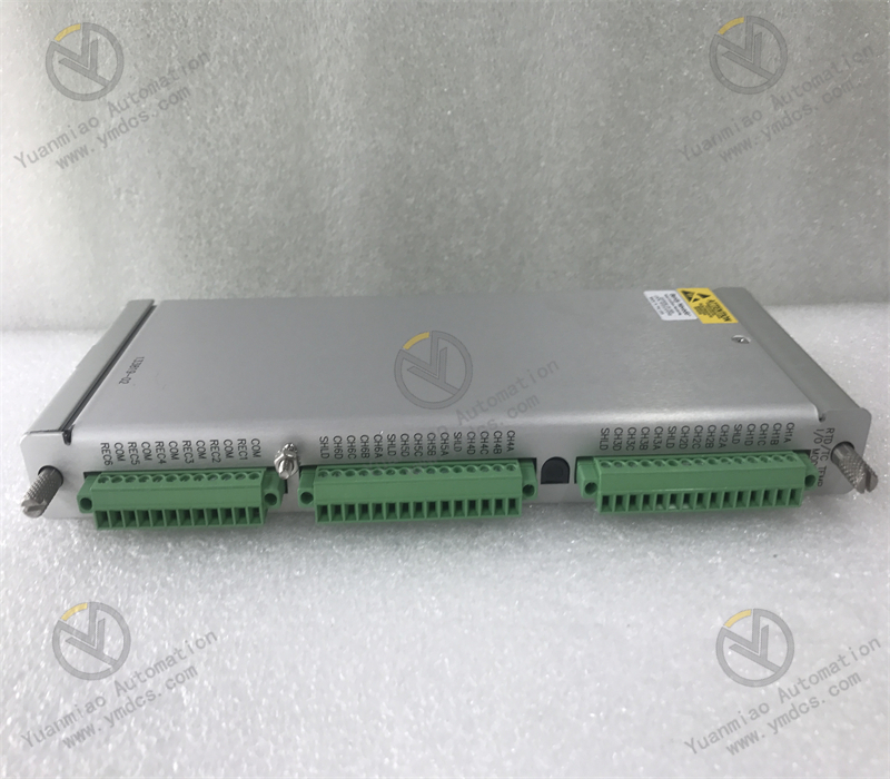
ABB EI801F 3BDH000015R1
I. Basic Information
1. Brand and Model
Brand: ABB
Model: EI801F 3BDH000015R1
Naming Convention:
Model: EI801F 3BDH000015R1
Naming Convention:
- EI: According to ABB's traditional naming logic, E represents Extension Module, and I represents Input Module, i.e., Input Extension Module.
- 801: Presumed to be a Digital Input Module (DI Module) (comparing with similar products like EI802F and EI813F, "801" may represent the basic model, number of channels, or voltage type).
- 3BDH000015R1: ABB product serial number for identifying the hardware version (R1 denotes Revision 1).
2. Type and Function
Type: Digital Input Module (DI Module), used to collect switching signals (e.g., ON/OFF states, contact open/close) from industrial field devices.
Core Function: Converts signals from external mechanical switches, sensors, etc., into binary data (0/1) for transmission to controllers (e.g., PLCs, DCS) for logical processing.
Core Function: Converts signals from external mechanical switches, sensors, etc., into binary data (0/1) for transmission to controllers (e.g., PLCs, DCS) for logical processing.
3. Application Scenarios
Compatible Systems: Distributed Control Systems (DCS) or PLC systems with controllers such as ABB AC 800M, AC 500-S.
Industries: Industrial automation, power systems, process control, machinery manufacturing, rail transit, and other scenarios requiring status monitoring.
Industries: Industrial automation, power systems, process control, machinery manufacturing, rail transit, and other scenarios requiring status monitoring.
II. Physical Characteristics
1. Dimensions and Weight
Dimensions: Referencing similar products (e.g., EI802F), approximately 120mm×80mm×35mm (compact design compatible with standard industrial control cabinets).
Weight: Approximately 0.15-0.2kg (lightweight for easy on-site installation and maintenance).
Weight: Approximately 0.15-0.2kg (lightweight for easy on-site installation and maintenance).
2. Installation and Indicators
Installation Methods:
- DIN Rail Mounting: Supports quick disassembly, compatible with standard industrial rails.
- Hot-Swapping: Supported by some models (verify specifications to avoid module damage).
Indicators:
- Power Indicator (PWR): Steady green indicates normal power supply.
- Channel Status Indicators: Each channel has an LED; illumination indicates valid signal input (e.g., contact closure).
- Fault Indicator (FAULT): Steady red or flashing indicates communication anomalies, hardware faults, or overload.
III. Electrical Characteristics
1. Power Supply and Consumption
Power Voltage: 24V DC (industrial-standard power supply supporting redundant inputs for enhanced reliability).
Power Consumption: Approximately 1-2W (low-power design reducing overall system energy consumption).
Power Consumption: Approximately 1-2W (low-power design reducing overall system energy consumption).
2. Input Channels
Number of Channels: Presumed to be 16 channels (similar to EI802F and EI813F; EI801F may be a basic version).
Signal Types:
Signal Types:
- Dry Contacts: Unpowered switch contacts (e.g., buttons, limit switches, relay contacts).
- Wet Contacts: Powered level signals (e.g., 24V DC proximity switch outputs).
Electrical Isolation:
- Optocoupler Isolation: Channel-to-channel or group-to-group isolation, resisting electromagnetic interference (EMI) with typical isolation voltage of 250V AC/DC.
- Anti-Misoperation Design: Protects against damage from external high-voltage surges.
3. Signal Processing
Response Time:
- Configurable signal filtering time (e.g., 1-20ms) to eliminate mechanical contact bounce (e.g., high-frequency tremors when buttons are pressed).
- Typical response time: <10ms (dry contacts), <5ms (wet contacts).
IV. Environmental Requirements
1. Temperature and Humidity Ranges
Operating Temperature: -25°C ~ +60°C (industrial-grade wide-temperature design for high-temperature workshops, cold storage, etc.).
Storage Temperature: -40°C ~ +85°C (no performance degradation during long-term storage).
Relative Humidity: 5% ~ 95% (non-condensing), dust and moisture resistant.
Storage Temperature: -40°C ~ +85°C (no performance degradation during long-term storage).
Relative Humidity: 5% ~ 95% (non-condensing), dust and moisture resistant.
2. Protection and Anti-Interference
Protection Class: IP20 (requires installation in control cabinets to prevent dust and splashes).
Vibration/Shock Resistance: Complies with IEC 61326 standards, suitable for industrial environments with mechanical vibrations (e.g., near production lines, compressors).
Vibration/Shock Resistance: Complies with IEC 61326 standards, suitable for industrial environments with mechanical vibrations (e.g., near production lines, compressors).
V. Communication and Functions
1. Communication Protocols
Default Bus: Supports ABB FIELDBUS (direct communication with AC 800M/AC 500-S controllers).
Extended Support: Adaptable to third-party fieldbuses such as Profibus DP, Ethernet/IP, Modbus via gateway modules (additional configuration required).
Extended Support: Adaptable to third-party fieldbuses such as Profibus DP, Ethernet/IP, Modbus via gateway modules (additional configuration required).
2. Core Functions
Real-Time Data Transmission: Converts input signals (0/1 states) to binary data and transmits them to the controller CPU via the backplane bus.
Diagnostic Functions:
Diagnostic Functions:
- Channel status monitoring (signal validity, open-circuit detection).
- Alarms for power failures, communication link anomalies; fault codes viewable via software like ABB Control Builder.
Functional Extensions:
- Sequence of Events (SOE): Some models support precise recording of signal change times (millisecond-level resolution, requires controller support).
- Redundant Configuration: Improves system reliability when paired with redundant controllers and bus modules.
VI. Working Principle
Signal Acquisition: Receives switching signals from field devices via terminal modules (e.g., TB series), filtered to remove high-frequency interference.
Signal Conditioning: Converts input signals (e.g., 24V DC) to internal logic levels (e.g., 5V) and isolates external electrical noise via optocouplers.
Data Encoding: Directly encodes digital signals into binary data ("1" = conduction, "0" = disconnection), stored in registers.
Communication Transmission: Sends data to the controller via the internal bus; the controller executes actions (e.g., alarms, interlocks) based on preset logic.
Self-Test Mechanism: Periodically checks power, channel, and communication status; triggers indicators and logs system errors when anomalies are detected.

VII. Typical Application Scenarios
Industrial Automation:
- Monitoring start/stop status of production line equipment, safety door switch detection, sensor signal acquisition (e.g., photoelectric switches, magnetic switches).
Power Systems: - Position feedback for circuit breakers and disconnectors, switch status monitoring in distribution cabinets, relay protection signal input.
Process Control: - Valve switch status, motor operation/fault signal acquisition, high/low level alarm input for storage tanks.
Mechanical Engineering: - Machine tool limit protection signals, robot IO signal interaction, equipment safety interlock signal access.
VIII. Common Faults and Troubleshooting
| Fault Type | Possible Causes | Troubleshooting Steps |
|---|---|---|
| No Power to Module | 1. Loose or disconnected power wiring 2. Faulty power adapter 3. Blown module fuse | 1. Check power connections 2. Replace power adapter 3. Contact technician for repair |
| Communication Interruption | 1. Damaged bus cable 2. Module address conflict 3. Incorrect protocol parameters | 1. Test cable continuity 2. Ensure unique module address 3. Verify baud rate, slave address |
| No Signal in Channel | 1. Faulty external switch 2. Loose terminal connections 3. Damaged optocoupler | 1. Measure switch continuity with multimeter 2. Tighten terminal screws 3. Replace channel or module |
| False Signal Reporting | 1. Electromagnetic interference (unshielded cables or poor grounding) 2. Insufficient filtering time 3. Aging components | 1. Check wiring distance from high-power equipment 2. Increase filtering time 3. Test insulation resistance |
| Module Overheating | 1. Inadequate ventilation 2. Internal component short circuit 3. Prolonged full-load operation | 1. Add cooling fans 2. Inspect component appearance after power-off 3. Optimize sy |