Description
1. Overview
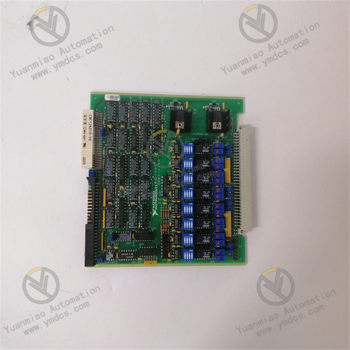
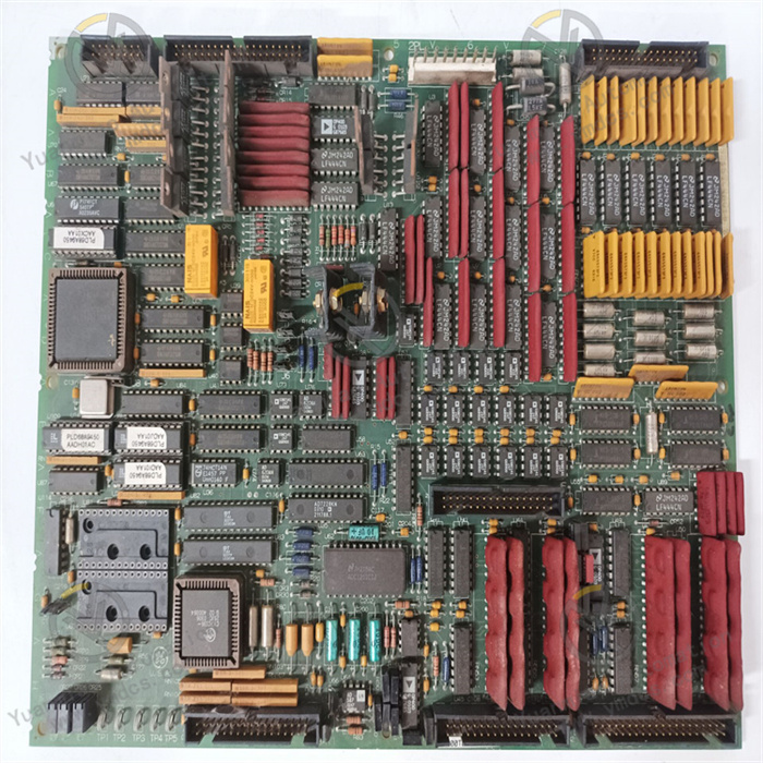
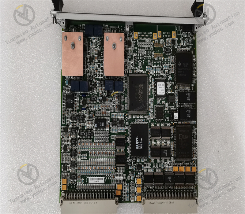
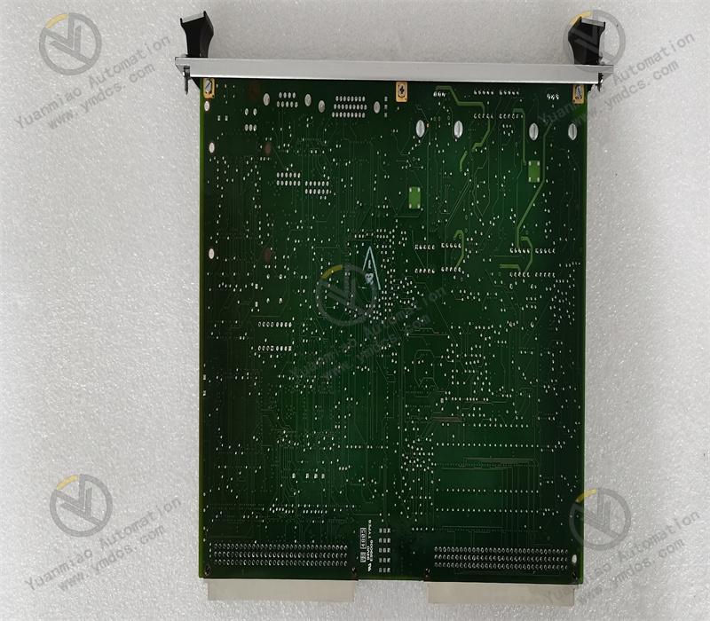
IS200BPIAG1AEB is an IGBT Bridge Personality Interface Board (BPIA) exclusively designed for the GE Vernova (formerly GE Energy) Speedtronic Mark VI turbine control system, serving as a core interaction board for variable frequency drive and power conversion systems of gas turbines and steam turbines.It performs signal interfacing, drive signal transfer, fault acquisition and link bridging between the AC drive control system and power electronic units, acting as a key intermediate hardware connecting the main control logic unit and three-phase IGBT power devices.The board accurately transmits gate drive signals, DC bus voltage feedback signals, shunt fault signals and various bridging control signals, and monitors the real-time operating status of power loops. It is suitable for working conditions including variable frequency speed regulation of high-power turbines, excitation power conversion and power adjustment during unit startup and shutdown.With high voltage withstand capability, fast signal response speed, full-link fault diagnosis and strong electromagnetic interference resistance, it is developed specifically for control systems of combined-cycle power plants equipped with gas turbines and steam turbines, ensuring stable, controllable and safe long-term operation of unit power drive loops.
2.1 Dedicated Power Bridging Architecture for Accurate Drive Signal Transmission
Customized bridging interface hardware for the Mark VI turbine system, it is engineered for three-phase IGBT AC drive loops and establishes a high-speed signal bridge between the control system and power electronic equipment.It stably and precisely forwards six channels of IGBT gate drive control signals, synchronously completes drive matching and timing calibration for three-phase (A/B/C) power devices, and guarantees synchronization and consistency of power switching actions.It effectively eliminates harmonics, power oscillation and device overheating caused by IGBT switching timing deviation, meeting high-precision power regulation requirements of large-capacity turbines.
2.2 Multi-Interface Integrated Design for Highly Centralized Loops
The board is equipped with a standard P1 rack connector and six vertical pin-type output interfaces (APL, BPL, CPL, AAPL, BAPL, CAPL), which correspond to signal connection with upper and lower bridge arm IGBTs of the three phases respectively, featuring neat interface layout and clear loop division.A single board integrates multiple functions including signal reception, signal shaping, drive transfer, fault collection and voltage feedback. No additional adapter boards are required, which greatly simplifies the wiring structure of the power control loop, reduces fault points in intermediate links, and improves the integration and stability of the entire power drive system.
2.3 Full-Link Fault Monitoring for Early Warning and Traceability of Power Loops
A complete online diagnosis mechanism for power loops is built in to collect fault information such as shunt faults, drive abnormalities, DC bus voltage drift, IGBT loop anomalies and link disconnection in real time, and upload data to the Mark VI main control system synchronously.It supports timestamped fault recording and precise fault point positioning, enabling quick troubleshooting of hidden risks including power device damage, poor contact in drive loops, signal mismatch and bus fluctuation.It facilitates predictive maintenance of power conversion systems and effectively prevents unit load reduction and trip shutdown accidents resulting from abnormal power loops.
2.4 High-Frequency Response to Adapt to Dynamic Regulation of High-Power Equipment
Embedded with high-speed signal processing and oscillation feedback circuits, the Voltage-Controlled Oscillator (VCO) for DC bus voltage feedback works within 0–20 MHz, delivering ultra-fast signal response and dynamic tracking performance.It perfectly adapts to dynamic operating conditions of turbines such as load variation, frequent startup/shutdown and instantaneous power fluctuation. It adjusts IGBT drive timing and output status rapidly following main control commands, ensuring real-time performance and linearity of unit power regulation, and enhancing power quality of power generation systems and unit operating efficiency.
2.5 Rigorous Industrial-Grade Protection for Harsh Power Plant Environments
Adopting military-grade PCB substrates and standardized industrial triple-proof (dustproof, moisture-proof, anti-corrosion) design, it offers dust resistance, moisture resistance, vibration resistance, temperature cycle resistance and electromagnetic interference immunity.It effectively suppresses electromagnetic noise and voltage surges generated by startup/shutdown of high-voltage equipment and inverters on site.The hardware contains no adjustable potentiometers, external fuses or test points, featuring solid structure, high reliability and low failure rate. It supports long-term continuous operation inside control cabinets and meets the requirement of 24/7 steady operation in power plants.
3. Specification Parameters
3.1 Basic Model Information
- Model: IS200BPIAG1AEB
- Brand & Series: GE Vernova Speedtronic Mark VI Turbine Control System
- Device Type: BPIA Bridge Personality Interface Board
- Core Functions: IGBT gate drive signal transfer, three-phase power loop bridging, DC bus voltage feedback, shunt fault monitoring and power link diagnosis
- Compatible Systems: Mark VI control systems for gas turbines, steam turbines and combined-cycle units
- Applicable Scenarios: Unit variable frequency drive, power conversion, excitation drive and high-power power electronic control loops
3.2 Electrical & Frequency Parameters
- Power Supply: Dual-mode 17.7 VAC / 5 VDC power input
- Feedback Frequency Range: DC bus voltage feedback VCO: 0 ~ 20 MHz
- Drive Channels: Six IGBT drive interfaces for upper and lower bridge arms of phase A/B/C
- Signal Characteristics: High-speed drive signal shaping, timing calibration and isolated transmission
- Monitoring Functions: Shunt fault detection, drive loop abnormality monitoring and DC bus voltage acquisition
- Hardware Structure: Integrated fixed design with no adjustable components, external fuses or test points
3.3 Interface & System Parameters
- Rack Interface: Standard P1 backplane connector compatible with Mark VI VME racks
- Power Interfaces: Six vertical male pin connectors (APL, BPL, CPL, AAPL, BAPL, CAPL)
- System Bus: Natively compatible with Mark VI proprietary control bus with high signal synchronization
- Data Functions: Drive signal transparent transmission, fault data upload, bus status feedback and link abnormality logging
- Configuration Support: Automatic matching of power loop parameters via official GE turbine control configuration software
3.4 Environmental Parameters
- Operating Temperature: -40 ℃ ~ +70 ℃
- Storage Temperature: -55 ℃ ~ +125 ℃
- Operating Humidity: 5% ~ 95% RH (non-condensing)
- EMC Compliance: Complies with industrial power plant EMC standards to resist heavy electromagnetic interference from high-power equipment
- Operation Mode: 24-hour non-stop continuous operation for long-term unattended unit supervision
3.5 Mechanical & Maintenance Parameters
- Mounting Method: Embedded installation in slot 13 / 21 of standard VME racks
- Structural Features: Highly integrated monolithic PCB with reinforced anti-vibration and anti-aging design
- Status Monitoring: On-board self-test of operating status, drive link identification and fault alarm upload
- Maintenance Compatibility: Online fault diagnosis, background log traceability and retrofit replacement for legacy units
- Protection Design: Industrial triple-proof protection for complex cabinet environments in power stations
Based on the power control architecture of the Mark VI turbine system, the IS200BPIAG1AEB implements a closed-loop power link interaction workflow: receiving main control drive commands → signal shaping and calibration → three-phase IGBT bridge transfer → power loop status collection → voltage feedback and fault reporting.
After power-on initialization, the board automatically completes hardware self-test, interface link verification, bus handshaking and power supply inspection. It enters normal power bridging operation only after confirming healthy drive interfaces, communication links and power supply.
During unit operation, the module receives IGBT switching drive instructions issued by the Mark VI main control system in real time. Control signals go through noise reduction, shaping and timing calibration, then are output synchronously to IGBT power devices on upper and lower bridge arms of phase A/B/C via six independent interfaces. It precisely controls switching timing and on/off status of the power loop to realize unit power conversion, variable frequency regulation and dynamic load adaptation.
Meanwhile, the module continuously collects DC bus voltage signals, loop shunt status and drive link conditions, and transmits analog feedback signals and status data back to the main control system at high frequency to form closed-loop power regulation.
The module monitors abnormal conditions of the power drive link throughout the operation. Once IGBT drive failure, loop short circuit, signal disconnection, over-limit bus voltage or shunt faults are detected, the abnormal channel is locked immediately, fault codes and event logs are uploaded, and the main control system is assisted to execute load limiting, alarming and interlock protection.Relying on high-precision signal transmission and full-link monitoring, it ensures accurate timing and stable operation of the turbine power drive loop, avoids power imbalance, device damage and unexpected unit trips, and supports safe, efficient and continuous operation of the unit.
5.1 Mark VI Main Control Systems for Gas & Steam Turbines
Widely used in Mark VI control systems of medium and large gas turbine and steam turbine generator units. As the core bridging board for power conversion loops, it transfers drive signals for IGBT power devices and monitors loop status. It guarantees precise and controllable power regulation during unit startup, load ramping, load reduction and steady-state operation, serving as the core hardware foundation for variable frequency drive and power control of turbines.
5.2 Power Conversion Systems for Combined-Cycle Power Plants
Suitable for high-power power electronic conversion loops of cogeneration and gas-steam combined-cycle power plants. Adapted to frequent load variation and dynamic power adjustment, it stabilizes unit output power and power quality through high-speed signal feedback and precise timing control, suppresses power fluctuation and harmonic interference, and improves power generation efficiency and operational stability of combined-cycle units.
5.3 Excitation & Variable Frequency Drive Systems for Generator Units
Applied to excitation drive and auxiliary equipment variable frequency speed control systems of large generator units. It performs signal transfer and fault monitoring for excitation power bridges and variable frequency power bridges to ensure stable operation of excitation and variable frequency drive loops, and eliminates unit excitation fluctuation and unstable auxiliary equipment operation caused by power device faults and abnormal drive signals.
5.4 High-Power Industrial Drive Control Systems in Power Plants
Adapted to variable frequency drive systems of large fans, water pumps, compressors and other high-power auxiliary equipment in power plants. As the core interface board for IGBT drive bridges, it ensures accurate switching actions, monitorable loop conditions and early fault warning for high-power frequency conversion equipment, improving reliability and controllability of industrial drive systems.
5.5 Retrofit & Spare Part Replacement for Legacy Mark VI Systems in Power Plants
As an original factory-standard BPIA interface board for GE Mark VI systems, it is perfectly compatible with control system upgrade, faulty board replacement and hardware iteration of turbine control systems in aging power plants. It fully matches the original rack, wiring logic and control programs without large-scale system reconstruction. Fast equipment renewal restores operating performance of power drive loops and cuts maintenance and renovation costs for power stations.
![]()