Description
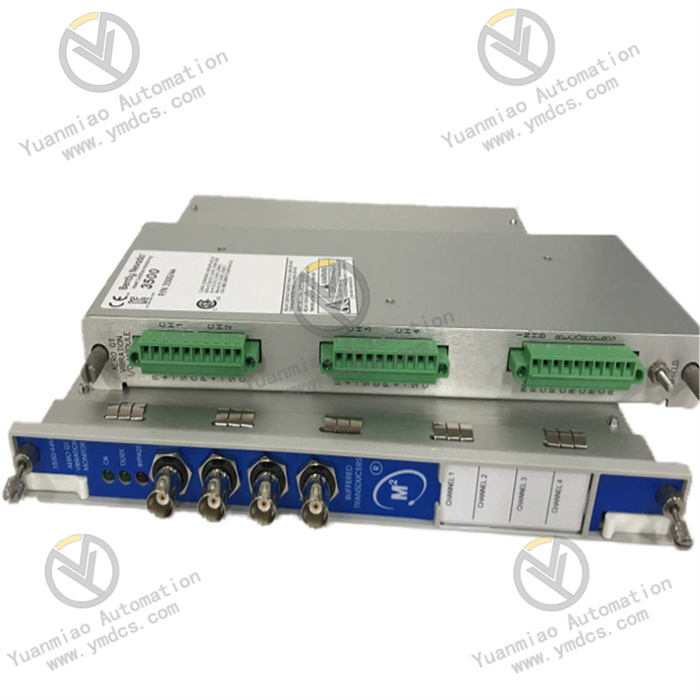
Bently Nevada 3500/90
Featuring an industrial-grade ruggedized design, the module delivers high-precision signal processing, flexible channel configuration, comprehensive alarm settings, and strong environmental adaptability. It is suitable for highly demanding industrial applications including power generation, petrochemicals, metallurgy, papermaking, and mining, where equipment monitoring accuracy and system reliability are critical. As a core monitoring module of the 3500 Series system, it is widely used for condition monitoring and protection of various critical rotating equipment. It is manufactured in the United States, with new original products typically supplied with a 12-month warranty, and weighs approximately 1 kg.
1. Positioning and System Relationship
- System AffiliationPart of the Bently Nevada 3500 Series Machinery Protection System, model 3500/90 is a 4-channel displacement monitor and is not designed for standalone operation. It must operate in conjunction with the 3500 Series system rack, main controller, Rack Interface Module (RIM), and Bently Nevada displacement sensors to form a complete rotating machinery displacement monitoring and protection chain. It is incompatible with other Bently Nevada series (such as the 1300 Series and 2300 Series) or third-party monitoring and control systems. It is one of the core components enabling multi-parameter comprehensive monitoring in the 3500 Series system, compatible with both full-size 3500 frames (14 monitor slots) and mini frames (7 monitor slots).
- Core RoleIt serves as the core for displacement parameter monitoring in the 3500 Series system. Its main responsibilities include: receiving input signals from Bently Nevada proximity displacement sensors, performing filtering, amplification, and conditioning on the signals to generate vibration and displacement measurements; supporting channel pairing configuration, allowing up to 2 monitoring functions at one time, where Channels 1 and 2 perform one function and Channels 3 and 4 perform either the same or a different function; comparing processed signals in real time with user-programmable alarm setpoints (Alert and Danger) and triggering alarms in case of abnormalities; providing operators and maintenance personnel with real-time operating information on equipment displacement parameters to facilitate early detection of abnormal conditions and prevent fault escalation; and coordinating with 3500 Series relay modules and communication gateway modules to achieve alarm interlocking and data uploading, ensuring the integrity and reliability of the monitoring system.
- Mounting PositionDesigned as a standard full-height module, it fits dedicated monitor slots in 3500 Series racks. It should be arranged in coordination with other modules in the frame (such as power supply modules and Rack Interface Modules) without requiring additional rack modifications. The module supports hot-swapping: when proper procedures are followed, it can be removed and replaced while the system is powered on without affecting the operation of other unrelated modules, facilitating on-site installation, commissioning, and later maintenance. It integrates standard interfaces for direct connection to the 3500 Series backplane bus, enabling high-speed data communication with other modules and ensuring stable and timely signal transmission.
- System ArchitectureAs the displacement monitoring core of the 3500 Series Machinery Protection System, it forms a complete monitoring chain with other system components and field devices:Bently Nevada proximity displacement sensors collect parameter signals such as radial vibration and axial displacement from rotating machinery → signals are transmitted to the 3500/90 monitoring module → the module performs signal filtering, amplification, conditioning, and measurement conversion → processed signals are compared in real time with preset alarm thresholds → alarms are triggered and monitoring data and alarm information are transmitted to the Rack Interface Module in case of abnormalities → the Rack Interface Module uploads data to the system main controller and host computer, while interlocking relay modules to execute protection actions.This forms a closed-loop monitoring system of “acquisition-processing-monitoring-alarm-interlocking”, providing comprehensive protection for the safe operation of rotating machinery.
2. Functions and Technical Features
1. Multi-Type Displacement Parameter Monitoring and High-Precision Signal Processing
The module offers flexible monitoring function compatibility. Each channel can be programmed via 3500 rack configuration software to monitor various displacement parameters, including radial vibration, axial displacement, differential expansion, shaft eccentricity, and rolling element bearing vibration (REBAM), fully covering the core requirements of rotating machinery displacement monitoring. Equipped with high-precision signal processing circuitry, it accurately receives input signals from proximity sensors. After filtering, amplification, and other processing, it generates stable and accurate measurements with excellent precision, capturing subtle changes in equipment displacement parameters to provide reliable data support for equipment condition assessment and fault diagnosis.
2. Flexible Channel Configuration and Alarm Setup
It features a 4-channel design with channel pairing configuration, supporting up to 2 monitoring functions simultaneously. Channels 1 and 2 form one group, and Channels 3 and 4 form another. Monitoring functions for each group can be flexibly configured according to on-site requirements to suit different types of rotating equipment. Using 3500 rack configuration software, two-level alarm thresholds (Alert and Danger) can be set for each active static measurement. Thresholds are adjustable based on equipment operating standards, enabling rapid alarm triggering during abnormalities to provide dual protection for equipment safety.
3. Hot-Swappable and High-Reliability Design
The module supports hot-swapping. When proper procedures are followed, it can be inserted or replaced while the system is powered on without disrupting other modules, greatly improving on-site maintenance efficiency and reducing unplanned downtime. Constructed with high-quality industrial-grade components, it provides excellent immunity to electromagnetic interference and voltage fluctuations, adapting to harsh industrial environments including high temperature, humidity, dust, and strong interference. It enables 24/7 uninterrupted stable operation with low failure rates, withstands demanding on-site conditions, and extends service life.
4. Complete System Coordination and Data Transmission
It integrates seamlessly with 3500 Series Rack Interface Modules, communication gateway modules, relay modules, and more to achieve high-speed monitoring data transmission and alarm interlocking. The module sends monitoring data and alarm information to the Rack Interface Module, which can connect to interface modules of other frames and host software in a daisy-chain topology for multi-frame data integration. It can also transmit data to external devices such as DCS and PLC via communication gateway modules, allowing operators to implement centralized monitoring and management.
5. Convenient Configuration and Maintenance Characteristics
3. Technical Specifications
| Category | Details |
|---|---|
| Product Identification | Model: Bently Nevada 3500/90; Type: 4-channel displacement monitor; Series: 3500 Series; Manufacturer: Bently Nevada (USA); Country of Origin: USA; HS Code: 8538900000; Application: Monitoring of displacement parameters such as radial vibration and axial displacement of rotating machinery; Warranty: 12-month warranty for new original products; Weight: Approx. 1 kg |
| Core Parameters | • Number of channels: 4 channels, supporting paired configuration (Channels 1–2 as one group, Channels 3–4 as another)• Monitoring functions: Configurable for radial vibration, axial displacement, differential expansion, shaft eccentricity, rolling element bearing vibration (REBAM)• Signal input: Accepts input from Bently Nevada proximity sensors• Configuration: Via 3500 rack configuration software for channel functions, alarm thresholds, and other parameters• Alarm setup: Two-level alarms (Alert, Danger) with adjustable thresholds• Compatibility: Coordinates with 3500 Series Rack Interface Modules, communication gateway modules, and relay modules |
| Physical Parameters | • Weight: Approx. 1 kg• Module type: Full-height module• Mounting: Front-insert type, compatible with standard 3500 Series rack slots• Plugging feature: Hot-swappable (live insertion/removal with proper procedures) |
| Environmental Rating | • Operating temperature: Suitable for harsh industrial environments (refer to official manual for specifics)• Protection: For cabinet mounting, with basic dustproof and moisture-proof performance• Immunity: Complies with industrial EMC standards, resistant to surges and on-site interference for stable signal transmission |
| Operating Characteristics | • Operation: Coordinates with 3500 Series system, supports 24/7 continuous operation• Data transmission: Communicates via 3500 backplane bus; data upload via Rack Interface Module and communication gateway modules• Maintenance: Modular design, hot-swappable, allowing quick replacement and service with minimal reconfiguration |
| Compatibility | Exclusively compatible with Bently Nevada 3500 Series Machinery Protection System, supporting full-size and mini frames; works with Bently Nevada proximity sensors, 3500 Series Rack Interface Modules, communication gateway modules, and relay modules; incompatible with other Bently Nevada series or third-party monitoring systems |
4. Compatible Systems and Supporting Components
1. Compatible Host Systems
2. Supporting Components
5. Application Scenarios
- Power Industry: Rotating machinery such as steam turbines and generators in thermal and nuclear power plants, monitoring parameters including radial vibration, axial displacement, and differential expansion to detect shaft anomalies early, ensure safe and stable unit operation, and prevent equipment damage caused by excessive displacement.
- Petrochemical Industry: Compressors, pumps, and other equipment in refineries and natural gas processing plants, monitoring vibration and displacement parameters to prevent failures such as equipment wear, misalignment, and unbalance, ensuring continuous and safe production.
- Metallurgy and Manufacturing: Large fans, hydraulic systems, transmission equipment, and steel production facilities, monitoring parameters such as shaft eccentricity and rolling element bearing vibration to optimize operating efficiency, extend service life, and reduce unplanned downtime.