Description
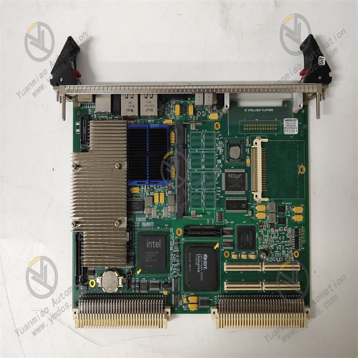
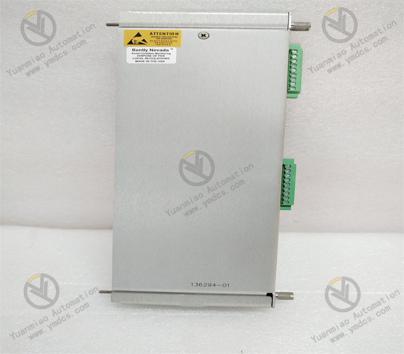
Abaco Systems VMIPCI-5565
I. Overview
The Abaco Systems VMIPCI-5565 is a high-performance PCI interface Reflective Memory communication card, compatible with host devices such as industrial control computers and real-time simulation workstations based on the PCI bus. It is widely used in fields with extremely high requirements for data transmission real-time performance and synchronization, including aerospace flight simulation, ship integrated control systems, industrial robot collaborative control, and power system real-time monitoring. By leveraging reflective memory technology, it enables low-latency and highly reliable data sharing among multiple nodes, serving as a key communication unit for building distributed real-time control systems.
With the core positioning of "high real-time communication, high synchronization accuracy, high-reliability redundancy, and wide scenario adaptability", the module achieves real-time mirroring and synchronous transmission of multi-node data through Abaco's independently developed reflective memory control chip and real-time communication protocol. In terms of core performance, it supports a maximum reflective memory communication rate of 1Gbps, with data transmission latency as low as hundreds of nanoseconds, meeting the real-time control requirements of millisecond or even microsecond levels; it adopts the PCI 2.2 standard bus interface, compatible with 32-bit/64-bit PCI slots, and adaptable to mainstream industrial control hosts; it is equipped with 16MB on-board reflective memory capacity, supporting real-time mapping of multi-node memory space and realizing an efficient transmission mode of "write once, share across multiple nodes"; it has dual-port fiber optic communication interfaces, supporting redundant topology to improve system communication reliability; it features node ID configuration, fault self-diagnosis and other functions, enabling real-time monitoring of communication link status to ensure rapid fault location and handling; it is compatible with multiple Abaco real-time operating systems (such as VxWorks, QNX) and mainstream industrial operating systems (such as Windows, Linux), significantly enhancing system integration flexibility.
The VMIPCI-5565 has undergone core optimizations in communication performance and reliability: the communication rate has been increased from 500Mbps to 1Gbps, doubling the data transmission efficiency and adapting to real-time transmission scenarios with large data volumes; the on-board memory capacity has been expanded from 8MB to 16MB, supporting large-capacity data sharing among more nodes; a new dual-port redundancy design has been added, which can automatically switch to the backup link when a single link fails, with communication interruption time ≤1ms; the synchronous clock circuit has been optimized, improving the multi-node synchronization accuracy to ±10ns to meet the requirements of high-precision collaborative control; the anti-electromagnetic interference capability has been enhanced, passing military-grade electromagnetic compatibility tests and adapting to applications in harsh electromagnetic environments.
II. Technical Specifications
| Parameter Category | Specification Parameters | Parameter Description |
|---|---|---|
| Basic Interface & Communication Parameters | Bus Interface | Interface standard: PCI 2.2, compatible with 32-bit/64-bit PCI slots; Bus frequency: 33MHz/66MHz (automatic adaptation); Data width: 32-bit (default)/64-bit (optional); Plug and Play: Supports PNP function, compatible with PCI bus specifications; Interrupt mode: Supports level-triggered/edge-triggered interrupts, configurable interrupt vector |
| Reflective Memory Characteristics | - | Memory capacity: 16MB on-board SDRAM, supporting ECC error checking; Memory mapping: Supports real-time mirroring of multi-node memory space, mapping latency ≤50ns; Access method: Direct CPU read/write, supporting DMA data transmission; Memory partitioning: Configurable 8 independent memory partitions, supporting isolated transmission of data with different priorities |
| - | Communication Interface | Interface type: Dual-port fiber optic interface (SC/ST optional); Communication rate: 1Gbps (full-duplex); Transmission distance: Multi-mode fiber ≤500m, single-mode fiber ≤10km (optional long-distance module up to 40km); Topology support: Supports ring, star, and bus topologies, maximum 64 nodes; Communication protocol: Abaco proprietary reflective memory protocol (compatible with VMEbus reflective memory standard) |
| - | Synchronization Interface | Interface type: BNC synchronous clock input/output; Synchronization signal: TTL level square wave, frequency 1Hz-10MHz (configurable); Synchronization accuracy: Synchronization error between multiple nodes ≤±10ns; Synchronization mode: Supports two modes: external clock input and master node clock output |
| Performance & Reliability Parameters | Communication Performance | Transmission latency: End-to-end transmission latency ≤300ns (16-byte data); Throughput: Maximum effective throughput 950Mbps (at 1Gbps link rate); Data frame format: Supports variable frame lengths from 64 bytes to 1500 bytes, default 128 bytes; Burst transmission: Supports burst transmission of data over 1MB, transmission efficiency ≥98% |
| - | Redundancy Performance | Redundancy mode: Dual-port link redundancy, supporting automatic fault switching; Switching time: Link fault detection time ≤500ns, switching completion time ≤1ms; Redundant topology: Supports two topology configurations: dual-ring redundancy and active-standby link redundancy; Fault recovery: Automatic re-synchronization after link recovery, no data loss |
| - | Diagnosis & Fault Tolerance | Diagnostic functions: Link status monitoring (optical power, bit error rate), memory ECC error detection, bus communication fault detection; Fault tolerance: Supports single-node fault isolation without affecting the entire communication network; Error alarm: Outputs fault alarm information through interrupt signals and status registers; Fault logging: Stores the latest 100 fault logs (including timestamps and fault types) |
| - | Reliability Indicators | Mean Time Between Failures (MTBF): ≥2.0×10⁶ hours (at 25℃ environment); Service life: ≥10 years; Data reliability: Transmission bit error rate ≤1×10⁻¹²; Memory reliability: ECC error correction capability (single-bit error correction, double-bit error detection) |
| Environmental & Protection Parameters | Environmental Adaptability | Operating temperature: 0℃ - 60℃ (commercial grade), -40℃ - 85℃ (industrial/military grade optional); Storage temperature: -55℃ - 125℃; Relative humidity: 5% - 95% (no condensation at 40℃); Altitude: ≤5000m (industrial grade), ≤15000m (military grade) |
| - | Protection & Anti-Interference | Protection level: IP20 (board-mounted installation); Housing material: Metal shielded housing; Anti-electromagnetic interference: Complies with MIL-STD-461F (military grade), IEC 61000-4 (industrial grade); ESD protection: Contact discharge ±8kV, air discharge ±15kV |
| - | Mechanical Stability | Vibration resistance: 10-2000Hz, 10g (tri-axial, military grade); Shock resistance: 50g, 1ms (half-sine wave, tri-axial, military grade); Installation method: Standard PCI board installation (167.6mm length × 106.7mm height); Weight: Approximately 180g |
| Software & Compatibility Parameters | OS Compatibility | Real-time operating systems: VxWorks 6.5+, QNX 6.6+, RTX 2016+; Industrial operating systems: Windows 7/10/11 (32/64-bit), Linux (Ubuntu 18.04+, CentOS 7+); Development environment: Supports C/C++, Python development interfaces |
| - | Software Tools | Configuration tool: Abaco Reflective Memory Configurator (graphical configuration of node ID, topology, memory partitioning); Diagnostic tool: Abaco Link Diagnostics (real-time monitoring of link status, throughput, bit error rate); Driver support: Provides standard API drivers and third-party simulation software interfaces (e.g., MATLAB/Simulink) |
III. Functional Features
1. 1Gbps High-Real-Time Communication to Meet Millisecond-Level Control Requirements
2. Dual-Port Redundancy Design to Ensure High Reliability of Communication Links
3. ±10ns High Synchronization Accuracy to Realize Multi-Node Collaborative Control
4. Flexible Topology & Partition Management to Adapt to Diverse Application Scenarios
5. Full-Link Diagnosis & Compatibility to Simplify Integration & Operation and Maintenance
IV. Installation & Debugging Guide
1. Installation Operation Steps
- Pre-installation Preparation: Confirm that the module model is Abaco VMIPCI-5565, with no external damage, no scratches on the fiber optic interface, and no oxidation on the gold fingers; prepare an industrial control host compatible with PCI slots (supporting PCI 2.2 or higher standard), multi-mode/single-mode fiber (selected according to transmission distance, OM3 multi-mode fiber is recommended), fiber jumpers (SC/ST connectors, matching the module interface), synchronous clock cables (BNC connectors), torque screwdrivers, fiber optic power meters, anti-static wristbands and other tools; check the installation environment: operating temperature 0℃-60℃ (commercial grade), no corrosive gas or strong electromagnetic interference, stable host power supply (220V±10%), and sufficient heat dissipation space reserved (≥5cm around the module).
Module Installation: Wear an anti-static wristband, turn off the host power and unplug the power cord; open the host chassis, select an idle PCI slot (32-bit/64-bit is acceptable), and remove the slot baffle; align the module's gold fingers with the slot and push it in smoothly to ensure full contact of the gold fingers, fix the module baffle with M3 screws, with a torque of 0.5-0.8N·m; install the dust cap for the fiber optic interface (do not connect the fiber for the time being), close the host chassis and connect the power cord.
Link Connection: Connect the fiber optic links according to the topology design — in the ring topology, "PORT 1" of each node is connected to "PORT 1" of the next node, and "PORT 2" is connected to "PORT 2" of the previous node to form a dual ring; in the star topology, "PORT 1" and "PORT 2" of all nodes are respectively connected to the corresponding ports of the fiber optic switch; use a fiber optic power meter to detect the link optical power (normal range -10dBm to -20dBm) to avoid burning the interface due to excessive optical power; synchronous clock connection: "SYNC OUT" of the master node is connected to "SYNC IN" of the slave nodes, or "SYNC IN" of all nodes is connected to an external clock source, ensuring reliable grounding of the shield layer of the clock cable.
- Hardware Check: Turn on the host power, start the host, and confirm that the module is normally recognized through the host BIOS or device manager (displaying "Abaco VMIPCI-5565 Reflective Memory Card"); if not recognized, check whether the module is installed in place, whether the PCI slot is faulty, and whether the host power supply is stable; use the fiber optic power meter to detect the optical power of each link again to confirm no abnormalities.
- Driver Installation: Download the corresponding version of the driver according to the host operating system (obtained from the Abaco official website), run the driver installation program, and complete the installation according to the wizard; after the installation is completed, start the Abaco Reflective Memory Configurator configuration tool, and confirm that the tool can recognize the module, displaying "Device Status: Normal".
2. Debugging Operation Process
Basic Parameter Configuration: Start the Configurator tool and enter the "Network Configuration" interface — node configuration: set the local node ID (1-64, ensuring uniqueness in the network) and node name (e.g., "FlightControl-01"); link configuration: set the communication rate (default 1Gbps) and port mode (active-standby redundancy/independent link); memory configuration: divide memory partitions (e.g., 8 partitions, 2MB each), and set the access permission (read-only/read-write) and synchronization strategy for each partition; synchronization configuration: select the synchronization mode (master node/slave node/external clock) and set the synchronization frequency (default 10MHz). After the configuration is completed, click "Save Configuration" and restart the module to take effect.
- Link Connectivity Test: Enter the "Link Diagnosis" interface, click "Full Node Scan", and the tool will automatically identify all nodes in the network (displaying node ID, name, and link status); select a node, click "Link Test", send 1000 frames of 16-byte test data, and check the "Transmission Success Rate" (should be ≥99.999%), "Average Latency" (should be ≤300ns), and "Bit Error Rate" (should be ≤1×10⁻¹²); simulate a link fault (unplug the active link fiber), and observe the tool displaying "Active Link Fault, Switching to Standby Link", with switching time ≤1ms and no decrease in transmission success rate.
Synchronization Accuracy Test: Connect an oscilloscope to the "SYNC OUT" interface of the master node and the "SYNC IN" interface of the slave node, measure the phase difference between the two clock signals, which should be ≤±10ns; enter the "Synchronization Diagnosis" interface, start the "Synchronization Accuracy Test", and the tool will display the clock deviation between each node and the master node, which should be within the range of ±10ns; write a test program through the API, the master node writes timestamp data to the reflective memory, and the slave node reads the data and calculates the time difference to verify the synchronization accuracy.
- Data Transmission Performance Test: Use the performance test tool provided by Abaco or write a test program by yourself — small data volume test: transmit 16-byte data 1 million times, record the average latency (should be ≤300ns) and throughput (should be ≥1 million frames/second); large data volume test: transmit 1MB data 1000 times, record the average latency (should be ≤500ns) and throughput (should be ≥950Mbps); multi-node collaboration test: 64 nodes write data to the same memory partition simultaneously, and verify the data synchronization consistency (no out-of-sequence or loss).
- System Joint Debugging: Integrate the module into the target system (such as a flight simulation system), and configure the data interaction rules of each node (e.g., node 1 writes attitude data to partition 1, and other nodes read data from partition 1); start the system, simulate normal working conditions (e.g., nodes write real-time control data), and check that the data synchronization of all nodes is normal and the latency meets the requirements; simulate fault conditions (e.g., fiber breakage, node fault), and check that the system automatically switches to the redundant link, the faulty node is isolated, and the core functions are not interrupted; run continuously for 72 hours, monitor the stable operation of the module, with no abnormalities such as link interruption or data error, and complete the debugging.
3. Daily Maintenance & Fault Handling
3.1 Daily Maintenance Specifications
- Daily Inspection: Check the link status (optical power, bit error rate), synchronization accuracy, and memory status through the diagnostic tool every day to ensure no abnormal alarms; check the cleanliness of the fiber optic interface every week, and wipe the interface with a dedicated fiber cleaning paper to avoid optical power attenuation caused by dust; check the heat dissipation of the module every month to ensure the normal operation of the host chassis fan, and the surface temperature of the module ≤60℃ (commercial grade).
- Regular Maintenance: Conduct link performance tests every quarter to check whether the transmission latency and throughput meet the requirements; replace the fiber jumpers every six months (especially in scenarios with frequent plugging and unplugging) to avoid link faults caused by jumper aging; conduct a comprehensive inspection of the module every year (such as ESD test, electromagnetic compatibility test), and calibrate the synchronization clock accuracy for industrial-grade modules.
- Special Environment Maintenance: In high-temperature environments (≥40℃), enhance heat dissipation by adding cooling fans; in dusty environments, clean the host chassis and module surface every month, and install dust caps on the fiber optic interfaces; in high electromagnetic interference environments, check the grounding of shielded cables to ensure the grounding resistance ≤1Ω.
3.2 Common Fault Handling
| Fault Phenomenon | Possible Causes | Handling Steps | Precautions |
|---|---|---|---|
| Module not recognized by the host | Improper module installation; Faulty PCI slot; Incorrect driver installation; Module hardware fault | Power off and reinstall the module to ensure full contact of the gold fingers; Replace the PCI slot for testing; Uninstall the driver and reinstall the corresponding version; Replace with a standby module for testing to confirm whether it is a hardware fault | The module must be installed with power off; The driver must match the operating system version |
| Link disconnection, alarm "Low Optical Power" | Contaminated fiber optic interface; Aging fiber jumper; Transmission distance exceeding specifications; Faulty optical module | Wipe the module interface and jumper connector with fiber cleaning paper; Replace with a new jumper for testing; Use a fiber optic power meter to detect the optical power and confirm whether it exceeds the transmission distance; Replace the optical module (original accessories required) for testing | Avoid scratching the fiber end face when cleaning the interface; The optical module must be replaced with power off |
| Excessive synchronization accuracy (>±10ns) | Loose synchronous clock cable; Faulty external clock source; Faulty module clock circuit | Replug and tighten the BNC synchronous cable; Detect the output signal (frequency, amplitude) of the external clock source; Replace with a standby module for testing to confirm whether it is a module fault | The synchronization cable must use a shielded cable; The external clock source must be calibrated regularly |
| Increased data transmission latency (>500ns) | Excessively high link bit error rate; Excessively high host CPU load; Unreasonable memory partition configuration | Detect the link bit error rate and replace the faulty link; Reduce the host CPU load (close irrelevant processes); Reconfigure the memory partitions (increase the capacity of high-priority partitions) | The CPU load of the real-time system is recommended to be ≤70%; The partition configuration must be optimized according to the data type |