Description
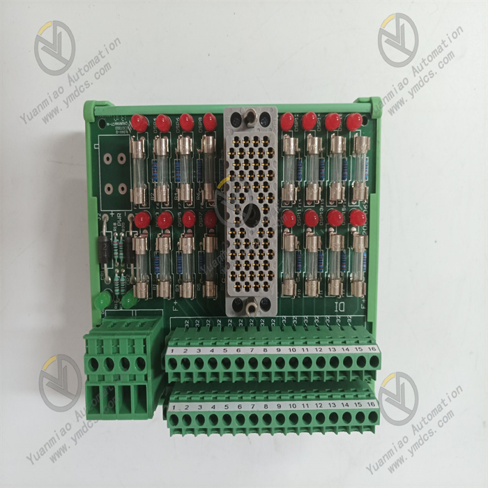
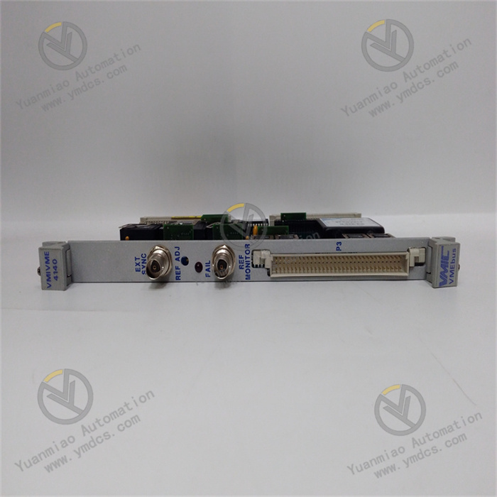
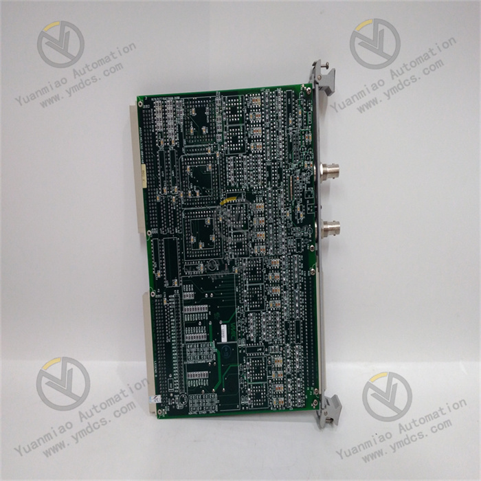
Abaco Systems VMIVME-4140-001
Overview
The Abaco Systems VMIVME-4140-001 is a high-performance board based on the VME (VersaModule Eurocard) bus architecture, playing a critical role in industrial automation, data acquisition, precision analog stimulation, and automatic test equipment (ATE). With its powerful analog output capabilities, it meets the high-precision signal output requirements of various complex application scenarios, providing a solid foundation for the stable operation and precise control of related systems. Since its market launch, it has been widely adopted in numerous industries due to its reliable performance.
Functional Features
Powerful Analog Output Capabilities
- Multi-Channel & High Resolution: Equipped with 32 analog output channels, each with 12-bit resolution, it can output or sink 10mA current at ±10V, delivering extremely fine analog signal outputs. This meets the needs of scenarios such as complex control signal output for multiple devices in industrial automation systems or precise feedback after multi-sensor analog signal acquisition in data collection systems.
- High-Precision D/A Conversion: Each output channel is equipped with a dedicated 12-bit D/A converter (DAC) to ensure high-precision analog output. Whether in precision analog stimulation applications with strict signal accuracy requirements (for simulating real environments or testing equipment performance) or in ATE for providing precise excitation signals to 被测 objects (DUTs), it operates stably to ensure the accuracy of system test results.
- Flexible Output Voltage Range: Supports software-selectable unipolar (0 to +10V, 0 to +5V, 0 to +2.5V) or bipolar (±2.5V, ±5V, ±10V) output voltage ranges, flexibly adapting to the input signal requirements of different devices and systems. In industrial automation control, it can easily adjust the output voltage mode and range according to the characteristics of the controlled object to achieve precise control.
Excellent Electrical Performance
- Low Output Impedance: With an output impedance of only 0.8Ω, it maintains signal stability and accuracy during transmission, reducing signal attenuation and distortion. This ensures good signal quality in long-distance transmission or complex electromagnetic environments, meeting the requirements of scenarios such as remote device control.
- Multiple Update Modes: Supports random update (non-scan) mode for sudden, irregular signal output needs in the system, as well as software or external synchronous update dual-buffered output. This enables precise synchronization in scenarios requiring collaborative work with other devices/systems, such as ensuring signal output synchronization in multi-device joint testing systems.
Convenient Calibration & Self-Test Functions
- Automatic Calibration: Can be initiated via system reset or software commands. During calibration, it automatically compiles and stores offset and gain coefficient tables, eliminating the need for manual tedious calibration. This significantly improves equipment maintenance and debugging efficiency, ensures the accuracy of output signals during long-term stable operation, and reduces signal deviation caused by untimely calibration.
- Self-Test Function: After system reset, the self-test function runs automatically, quickly determining whether the device is operating normally and displaying the self-test pass/fail result. If a fault exists, it accurately indicates the faulty channel. After self-test, the front-panel status LED intuitively displays the system status and self-test result, helping operators quickly understand the device condition and promptly identify and resolve issues. For example, during device startup, the automatic self-test function rapidly determines whether the device can be put into use, avoiding production delays or test errors caused by potential device failures.
Rich Connection & Expansion Capabilities
- Flexible Cable Connection Modes: Supports discrete wires or bulk-terminated cables, facilitating integration with field devices or systems. This enables easy implementation in complex industrial automation production lines (connecting various distributed actuators and sensors) or laboratory environments (building data acquisition and control systems), reducing system cabling difficulty and costs.
- PMC Expansion Site: Equipped with a PMC expansion site (PCI-X, 66 MHz), it can easily expand more functions based on actual application needs. For example, in ATE, expanding relevant functional modules can increase the testing capability for different types of DUTs; in industrial automation control systems, expanding communication functional modules can enhance the communication efficiency and compatibility with other devices.
Working Principle
Analog Signal Output Process
- Digital Signal Input: When the system requires analog signal output, external devices or systems transmit the digital signals to be converted to the VMIVME-4140-001 board via the VME bus. These digital signals contain various information for the required analog output, such as voltage amplitude, polarity, and other parameters.
- D/A Conversion: The 12-bit D/A converter of each channel on the board receives the digital signal and converts it into the corresponding analog voltage signal based on the digital signal value. For example, if the input digital signal indicates an output requirement of +5V, the D/A converter converts the digital quantity into the corresponding analog voltage value and outputs it to the corresponding channel.
- Signal Conditioning & Output: The converted analog signal undergoes a series of circuits for impedance matching and signal quality optimization. With the board's output impedance of only 0.8Ω, it ensures the signal is output in good condition. Finally, the analog signal is output to external devices via discrete wires or terminated cables, achieving control of external devices or signal excitation—such as driving actuators in industrial automation systems or providing test signals for DUTs in ATE.
Calibration & Self-Test Principle
- Automatic Calibration: When the automatic calibration function is initiated, the board's internal circuits generate a series of specific test signals and output them to each channel. Simultaneously, the board collects the actual output signals of each channel through internal feedback circuits and compares them with preset standard signals. Based on the comparison results, it calculates the offset and gain errors of each channel and generates offset and gain coefficient tables stored in the board's internal memory. During subsequent normal signal output, the board uses these tables to perform real-time corrections on the output signals to ensure accuracy.
- Self-Test Function: After system reset, the self-test circuit activates, sending self-test commands and test signals to key components and circuit modules of the board, including D/A converters, signal conditioning circuits, communication interfaces, etc. Each component and module performs corresponding self-test operations upon receiving the test signals and feeds back the results to the self-test circuit. The self-test circuit determines whether the device is operating normally based on the feedback. If a fault exists, it identifies the specific faulty channel or module and indicates it through the front-panel status LED in a specific display mode, enabling technicians to quickly locate and resolve issues.
Common Faults and Solutions
| Fault Symptom | Possible Causes | Solutions |
|---|---|---|
| Analog output signal abnormality (e.g., inaccurate voltage, large signal fluctuations) | 1. Calibration data loss or error (caused by unexpected power outages, system failures, etc.). 2. D/A converter failure (hardware damage due to long-term use or electrical surges). 3. Signal interference (strong surrounding electromagnetic interference affecting signal transmission and conversion). | 1. Reperform automatic calibration: Initiate the function via system reset or software commands to regenerate and store calibration data, restoring signal output accuracy. 2. Replace the D/A converter: If hardware failure is confirmed, contact professional maintenance personnel to replace the corresponding D/A conversion chip. 3. Investigate and eliminate interference sources: Check for high-power electrical equipment or other interference sources around the device, and adopt shielding/grounding measures (e.g., shielding signal cables, ensuring proper device grounding) to reduce electromagnetic interference. |
| No output signal from a specific channel | 1. Open circuit in the channel connection: Cable breakage due to aging or external force. 2. Hardware failure in the channel: Damage to circuit components corresponding to the channel (e.g., resistors, capacitors). | 1. Inspect and repair connection lines: Carefully check the channel's cable; replace or repair it if an open circuit is found. 2. Detect and replace faulty hardware: Use professional testing equipment to locate the hardware fault point (e.g., replace damaged resistors or capacitors). If self-diagnosis is impossible, contact Abaco Systems technical support for assistance. |
| Abnormal front-panel status LED display (e.g., constant on or off) | 1. Damaged LED: Aging due to long-term use. 2. Self-test circuit failure: Issues in the self-test circuit preventing correct LED control. | 1. Replace the LED: If the LED is damaged, replace it with one of the same specifications. 2. Repair the self-test circuit: Contact professional technicians to inspect and repair the self-test circuit, troubleshooting short circuits, open circuits, or other issues, and replace faulty components. |
| Board failure to communicate with the system via VME bus | 1. Loose VME bus connection: Plug not securely fastened during installation or maintenance. 2. Incorrect communication protocol settings: Mismatched communication protocol parameters between the system and the board. 3. Board communication interface failure: Hardware damage to the VME bus communication interface on the board. | 1. Re-tighten the VME bus connection: Check and re-plug the VME bus connector to ensure a secure connection. 2. Check and correct communication protocol settings: Verify parameters (e.g., data transmission rate, address allocation) to ensure consistency between the system and the board. 3. Repair or replace the communication interface: If hardware failure is confirmed, contact Abaco Systems technical support to repair or replace the VME bus communication interface module on the board. |