Description
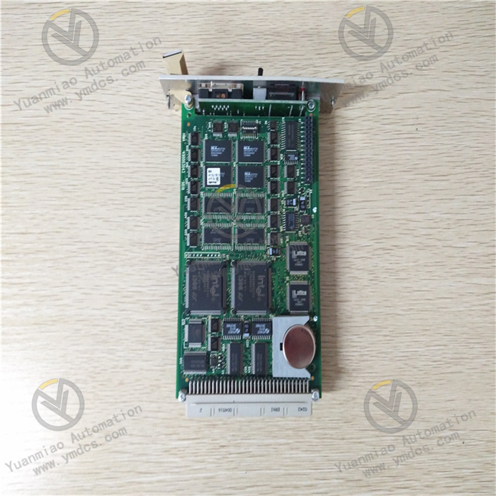
ABB DP620 3BHT300016R1
I. Overview
The ABB DP620 3BHT300016R1 is a pulse counting module, with its core positioning as a specialized data acquisition unit for accurate measurement of pulse signals, frequency and time intervals. Designed specifically for data acquisition needs in complex industrial automation scenarios, this module is equipped with 4 independent pulse input channels. Relying on a 32-bit high-precision counting core, it can achieve accurate capture and measurement of long-cycle and high-frequency pulse signals, and is widely used in core industrial fields such as iron and steel, power, metallurgy, chemical industry, petrochemical industry, papermaking, mining and nuclear power.
II. Product Features
32-bit High-precision Counting Capability: Equipped with a 32-bit high-precision counting core, each channel has a maximum counting frequency of up to 100kHz. It can accurately measure long-cycle pulse signals, instantaneous frequency and time intervals without the risk of counting overflow, meeting the high-precision data acquisition needs in industrial scenarios.
Strong Anti-interference and Signal Isolation: Built-in optocoupler isolation circuit can effectively suppress electromagnetic interference (EMI), voltage fluctuations and ground loop interference in industrial sites, ensure stable transmission of pulse signals under complex working conditions, and protect the internal circuit of the module from damage caused by external abnormal signals.
Flexible Configuration and Multi-mode Adaptability: Supports flexible setting of input filter time, counting direction (up/down) and gate trigger mode via PROFIBUS bus or dedicated configuration software. It is compatible with TTL/CMOS level signals and can adapt to NPN/PNP type sensors, meeting the needs of different application scenarios.
Real-time Data Transmission and Fast Response: With a response time of less than 10ms, it can quickly capture pulse signals and complete data processing. The measurement data is uploaded to the main control system in real time through the RS-485 interface, providing data support for real-time monitoring and precise control of the production process.
Built-in Self-test and Fault Diagnosis: Equipped with a complete built-in self-test function, it can real-time monitor faults such as input signal abnormalities (open circuit, distortion) and communication link interruption, generate fault prompts in a timely manner and feed them back to the main control system, facilitating maintenance personnel to quickly locate problems and reduce operation and maintenance costs.
- Wide Adaptability and High Reliability: Adopting industrial-grade component packaging design, it is suitable for 24V DC±10% wide voltage power supply, with an operating temperature range of -20℃ to +60℃ and an IP20 protection level. It can operate stably in industrial environments with much dust and large temperature differences. An optional ATEX explosion-proof certified version is available for explosion-proof scenarios.
III. Technical Parameters
| Parameter Name | Specification |
|---|---|
| Product Model | ABB DP620 3BHT300016R1 |
| Communication Interface | RS-485, supporting PROFIBUS protocol |
| Input Channels | 4 independent pulse input channels, with mutual isolation between channels |
| Counting Frequency | Maximum 100kHz per channel |
| Counting Resolution | 32-bit high-precision counter |
| Input Signal | Supports TTL/CMOS level, compatible with NPN/PNP type sensors |
| Power Supply | 24V DC ±10% |
| Operating Temperature | -20℃ to +60℃ |
| Storage Temperature | -40℃ to +85℃ |
| Protection Level | IP20 (module body) |
| Dimensions | 120mm (length) × 100mm (width) × 30mm (height) |
| Module Weight | Approximately 0.3kg |
IV. Working Principle
The core working principle of the ABB DP620 3BHT300016R1 pulse counting module is a closed-loop process of signal acquisition - isolation and filtering - high-precision counting - data transmission - fault monitoring. Through the coordinated operation of the optocoupler isolation module, counting control module, communication module and self-test module, it realizes accurate measurement and data interaction of pulse signals. The specific working process can be divided into five core stages:
The pulse signals output by external sensors (NPN/PNP type) are connected through the module input terminals, and first pass through the built-in optocoupler isolation circuit, which cuts off the electrical connection between the external circuit and the internal core circuit, filters out electromagnetic interference clutter, ensures the purity and stability of the input signals, and protects the internal circuit safety at the same time.
The isolated pulse signals pass through a configurable filter circuit, which filters out high-frequency interference pulses and signal glitches according to the preset filter time, shapes the distorted signals, and outputs standard rectangular pulse signals to provide guarantee for subsequent accurate counting. The filter parameters can be flexibly adjusted through software to adapt to different signal characteristics.
The 32-bit counting control module receives the shaped standard pulse signals, performs real-time counting of the pulse signals according to the preset counting direction (up/down) and gate control mode, and can calculate the pulse frequency (number of pulses per unit time) and time interval (duration between adjacent pulses) at the same time. The counting data is stored in the internal buffer in real time without overflow risk.
The communication module uploads the counting data in the buffer to the main control system (DCS/PLC) in real time through the RS-485 interface and PROFIBUS protocol, and receives configuration commands issued by the main control system (such as counting mode switching, parameter reset) at the same time, completing module configuration adjustment and two-way data interaction, with the response time controlled within 10ms.
V. Common Fault Troubleshooting
1. No Counting Data, No Feedback from Main Control System
2. Inaccurate Counting Data with Deviation
3. Communication Interruption, Unable to Interact with Main Control System
4. Module Fault Alarm, Self-test Abnormality