Description
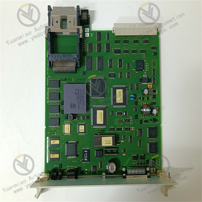
GE IS215VPROH1BD
I. Overview
The GE IS215VPROH1BD is a process control module and a key control component of the Mark VIe series control system. It is tailor-made for precision control scenarios in large-scale complex process industries such as power generation, petrochemicals, and metallurgy. Adopting a high-performance industrial-grade hardware architecture, this module integrates multi-channel signal processing, high-speed logic calculation, precise control output, and all-round anti-interference design. It enables real-time monitoring and closed-loop control of key parameters (e.g., temperature, pressure, flow rate, liquid level) in complex industrial processes.
II. Functional Features
The GE IS215VPROH1BD deeply integrates GE’s core technologies in the field of process control. To meet the control needs of complex industrial scenarios, it has the following core functional features:
- Multi-Channel High-Precision Signal Processing:Equipped with 16 analog input channels, it supports the acquisition of 4-20mA DC standard current signals, 0-10V DC standard voltage signals, and RTD (PT100/PT1000) temperature signals, enabling accurate capture of various key process parameters in industrial processes. The analog acquisition accuracy reaches ±0.02% FS, and the sampling refresh rate is increased to 250Hz, which can quickly respond to subtle parameter fluctuations and provide microsecond-level precise data for control decisions. Additionally, it is configured with 32 digital input channels (24V DC) for collecting discrete signals such as limit switch signals, solenoid valve feedback, and emergency stop signals. The input circuit adopts a 3000V AC photoelectric isolation design, which effectively resists strong electromagnetic interference and surge impacts in industrial sites, ensuring the stability of signal acquisition.
- High-Precision Control Output Capability:It has 12 analog output channels (configurable for 4-20mA DC/0-10V DC) with an output accuracy of ±0.05% FS and a load driving capacity of up to 800Ω. These channels can directly drive control components such as valve positioners, actuators, and frequency converters, realizing fine adjustment of process parameters. Equipped with 24 digital output channels, it adopts a dual-mode output of transistor + relay (transistor output rating: 1A/24V DC; relay output rating: 5A/250V AC) and supports independent configuration as normally open/normally closed mode, which can meet the control needs of different load types. The output circuit has a built-in triple protection mechanism against overcurrent, short circuit, and overvoltage. When the load is abnormal, it quickly cuts off and locks the output, and can be reset through software or local operation after the fault is eliminated.
- High-Speed Calculation and Flexible Control Logic:It is equipped with a GE-customized 32-bit dual-core industrial MCU with a core operating frequency of 500MHz, supporting real-time calculation of complex control algorithms such as PID (Proportional-Integral-Derivative), fuzzy control, cascade control, and feedforward control. The module has a built-in 1MB program storage space and 4MB data storage space, which can store multiple sets of control logic schemes and support online switching of operation modes. Through the GE ToolboxST configuration software, drag-and-drop programming can be used to build control logic. The software has a built-in rich library of process control function blocks (e.g., flow accumulation, temperature compensation, pressure correction), which greatly reduces the difficulty of development.
- Redundant Communication and System Integration Capability:It adopts a dual-redundancy communication architecture of EtherNet/IP + Profinet, with 4 communication ports (2 EtherNet/IP ports + 2 Profinet ports) and a maximum communication rate of up to 1Gbps. It supports master-slave communication, peer-to-peer communication, and automatic redundant link switching, ensuring the real-time performance and reliability of data transmission. It can be directly connected to the Mark VIe control system to realize data interaction with the main controller and other control modules; at the same time, it is compatible with general industrial protocols such as Modbus RTU/TCP and OPC UA, supporting seamless integration with third-party SCADA systems and MES systems, and realizing centralized management, remote monitoring, and data analysis of process data.
- Full-Dimension Fault Diagnosis and Redundancy Protection:Built with an enhanced self-diagnosis module, it real-time monitors the module’s power supply status, communication link integrity, signal quality of input/output channels, core circuit temperature, and operation unit status. When issues such as channel failure, communication interruption, power supply abnormality, or component overheating are detected, it can trigger an alarm within 3ms, upload fault codes, fault locations, and detailed causes through the communication interface, and light up the corresponding LED fault indicator, facilitating maintenance personnel to quickly locate the fault. It supports module-level hot redundancy configuration; the main and standby modules realize real-time data synchronization through a dedicated synchronization interface. When the main module fails, the standby module can automatically switch seamlessly within 5ms, ensuring uninterrupted control processes.
- Industrial-Grade Enhanced Reliability Design:It uses components selected for a wide temperature range, with an operating temperature range of -40℃~85℃ and a storage temperature range of -55℃~100℃, which can adapt to extreme industrial environments such as high-temperature workshops and low-temperature outdoor areas. The interior of the module adopts a modular circuit layout and an independent heat dissipation system; the heat sink is closely attached to power components, and combined with an intelligent temperature-controlled fan (automatically activated when the temperature ≥50℃), it effectively controls the temperature rise of core components. The housing is made of high-strength flame-retardant aluminum alloy with an IP20 protection rating, and has vibration resistance (5-500Hz, 2g acceleration) and impact resistance (20g, 11ms) capabilities. It complies with the IEC 61000-6-2/4 industrial electromagnetic compatibility standard and UL safety certification, with a Mean Time Between Failures (MTBF) of more than 200,000 hours.
- Convenient Configuration and Operation & Maintenance Management:It supports parameter configuration, control logic programming, fault diagnosis, and firmware upgrade through the GE ToolboxST configuration software. The software has a built-in offline simulation function, which can verify the rationality of the control logic in advance. The front of the module is equipped with a 3.5-inch color LCD display and 8 operation buttons, which can locally display real-time parameters of each channel, control curves, module operation status, and fault information, and support local parameter fine-tuning, control mode switching, and fault reset. It supports online debugging and remote operation & maintenance, allowing parameter modification and firmware upgrade without disconnecting the system power supply, which greatly improves the operation & maintenance efficiency.
III. Technical Parameters
| Parameter Category | Parameter Name | Specific Parameters | Unit |
|---|---|---|---|
| Basic Parameters | Model | GE IS215VPROH1BD | - |
| Overall Dimensions (L×W×H) | 260×190×90 | mm | |
| Weight | Approximately 2.2 | kg | |
| Installation Method | Rack-mounted (compatible with GE Mark VIe standard cabinet) | - | |
| Power Supply Parameters | Power Supply Voltage | Dual-power input: DC 24V (±15%) / AC 110-220V (±10%) | V |
| Rated Power Supply Current | DC 5A / AC 2A | A | |
| Power Consumption | ≤120W | W | |
| Power Supply Redundancy | Supports automatic switching of dual-channel independent power input redundancy | - | |
| I/O Parameters | Analog Input Channels | 16 channels, 4-20mA DC/0-10V DC/PT100/PT1000, ±0.02% FS accuracy | Channel |
| Digital Input Channels | 32 channels, 24V DC, 3000V AC photoelectric isolation | Channel | |
| Analog Output Channels | 12 channels, configurable for 4-20mA DC/0-10V DC, ±0.05% FS accuracy, 800Ω load | Channel | |
| Digital Output Channels | 24 channels: 8 transistors (1A/24V DC) + 16 relays (5A/250V AC) | Channel | |
| Isolation Voltage | 3000V AC (mutual isolation between input/output/power) | V | |
| Sampling Refresh Rate | 250Hz (analog input), 0.5ms (digital input) | Hz/ms | |
| Control Cycle | Minimum 1ms, configurable (1-100ms) | ms | |
| Communication & Reliability Parameters | Communication Interfaces | 2 EtherNet/IP ports + 2 Profinet ports, supporting redundancy | Port |
| Communication Rate | EtherNet/IP: 1Gbps; Profinet: 1Gbps | bps | |
| Operating Temperature Range | -40~85 | ℃ | |
| Storage Temperature Range | -55~100 | ℃ | |
| Mean Time Between Failures (MTBF) | ≥200,000 | Hour |
IV. Working Principle
Based on the closed-loop control process of "signal acquisition - data processing - logic calculation - command output - communication interaction - fault protection", the GE IS215VPROH1BD realizes precise control of complex industrial processes. The specific working principle is as follows:
- Multi-Type Signal Acquisition Stage:Various sensor signals from industrial sites (such as 4-20mA signals from pressure sensors, PT100 signals for temperature, and 24V DC signals from limit switches) are connected to the corresponding input channels of the module. The analog input channels have built-in high-precision signal conditioning circuits, which filter, amplify, and linearize the signals; for RTD signals, cold-junction compensation is performed to eliminate on-site electromagnetic interference and temperature drift errors. Then, a 24-bit high-precision A/D converter converts the analog signals into digital signals; the digital input channels are isolated by a photoelectric isolation circuit and then shaped by a Schmitt trigger to ensure the integrity of discrete signals.
- The collected digital signals are transmitted to the core control unit (dual-core MCU) through the internal high-speed data bus, completing the signal acquisition process. The analog acquisition delay is ≤3ms, and the digital response time is ≤0.5ms, ensuring the real-time performance of data.
- Data Processing and Logic Calculation Stage:The core MCU performs calibration and scaling conversion on the collected digital signals, converting the raw data into actual physical quantities (e.g., converting 4-20mA signals into pressure values of 0-10MPa, and PT100 signals into temperature values of -50~500℃). Then, according to the pre-configured control logic (such as PID adjustment algorithm and cascade control strategy), it performs calculations based on real-time collected parameters and set values to generate precise control commands. For example, when the temperature of the reaction kettle is lower than the set value, an analog command to increase the heating power is output after calculation; when the liquid level exceeds the upper limit, a digital command to close the feed valve and an alarm signal are generated.
- The MCU simultaneously runs a self-diagnosis program to real-time monitor parameters such as power supply voltage, communication signal strength, channel current/voltage, and core temperature, and compares them with preset thresholds. If an abnormality is detected, it immediately generates fault information and marks the fault type.
- Control Command Output Stage:The control commands generated by the MCU are transmitted to the output channels: the analog commands are converted into 4-20mA/0-10V standard signals by a 24-bit D/A converter, amplified by a power drive circuit, and then output to actuators (such as valve positioners and frequency converters) to adjust process parameters; the digital commands control the action of transistors/relays through drive chips, outputting switch signals to controlled equipment (such as feed pumps and alarm lights) to realize start-stop or state switching of the equipment.
- The output channels have a built-in triple protection circuit. When overcurrent, short circuit, or overvoltage is detected, the output circuit is quickly cut off and locked, and fault information is reported at the same time; after the fault is eliminated, the output can be restored through software or local button reset.
- Communication Interaction and Data Synchronization Stage:The module establishes a redundant communication link with the Mark VIe main controller through the EtherNet/IP/Profinet interface, and uploads real-time parameters, operation status, and fault information according to the configured cycle (1-100ms). At the same time, it receives control logic, set values, and other commands issued by the main controller. In addition, it communicates with third-party systems through compatible protocols to realize data visualization and remote control.
- In the redundancy configuration, the main and standby modules realize real-time synchronization of collected data, control commands, and operation status through a dedicated synchronization interface. The main module sends a heartbeat signal every 0.5ms, and the standby module monitors in real time to ensure data consistency.
- Redundancy Switching and Fault Handling Stage:When the main module fails (such as communication interruption, power failure, core abnormality, etc.), the standby module detects the loss of the heartbeat signal or fault information within 5ms, immediately switches to the working state, and takes over all control and communication tasks to ensure uninterrupted control. The faulty module is automatically isolated to avoid affecting the system.
- While the fault information is uploaded to the control system, the local color LCD displays the fault code, location, and cause, and the corresponding LED flashes to alarm. Maintenance personnel can troubleshoot the fault through the configuration software or local operation.
V. Common Faults and Troubleshooting Methods
| Fault Phenomenon | Fault Code | Possible Causes | Troubleshooting Methods | Precautions |
|---|---|---|---|---|
| No response after module power-on, power indicator not on | None | 1. Both dual-channel power supplies are not connected or terminals are loose; 2. Power supply voltage is out of the rated range; 3. Power module is burned out; 4. Fuse of the power circuit is blown; 5. Power switching circuit is faulty | 1. Check the wiring of the dual-channel power cables and fasten the terminals; 2. Measure the voltage with a multimeter to ensure it meets DC 24V±15% or AC 110-220V±10%; 3. Switch to the standby power supply; if there is still no response, contact GE after-sales to inspect the power module; 4. Remove the housing and replace the fuse with the same specification (10A/250V AC); 5. Contact after-sales to repair the power switching circuit | Before replacing the fuse, check the short-circuit point; special tools are required to remove the housing; dual-channel power supplies must be connected to independent circuits to ensure effective redundancy |
| Large deviation or fluctuation of analog input data | ERR-01 (Analog Input Fault) | 1. Loose or poor contact of sensor wiring; 2. Sensor failure; 3. Input cable is unshielded or poorly grounded; 4. Faulty signal conditioning circuit; 5. Lost calibration parameters; 6. Channel is interfered | 1. Fasten the wiring between the sensor and the module; 2. Connect a standard signal source to the channel for verification; replace the sensor if abnormal; 3. Replace with shielded twisted-pair cables and ensure single-point grounding of the shield layer; 4. Contact after-sales to inspect the conditioning circuit; 5. Re-calibrate through ToolboxST; 6. Route away from high-voltage cables or add shielding measures | A standard signal source with an accuracy of ≥0.01% is required for calibration; multi-point grounding of the shield layer is prohibited; RTD calibration must be performed with a standard temperature source |
| Communication interruption, unable to interact with the main controller/third-party system | ERR-03 (Communication Fault) | 1. Damaged communication cable or incorrect wiring; 2. Mismatched communication parameters (IP address, baud rate); 3. Damaged communication interface; 4. Faulty main controller port; 5. Both redundant links are faulty; 6. Protocol compatibility issues | 1. Replace with a dedicated shielded communication cable and verify the wiring; 2. Check parameters through the configuration software to ensure consistency with the system; 3. Switch to the standby communication interface; if the fault persists, contact after-sales for maintenance; 4. Switch to the standby port of the main controller; 5. Repair the redundant links; 6. Confirm the protocol configuration is correct; update the firmware if necessary | The module must be restarted for modified parameters to take effect; the correct subnet mask must be configured for EtherNet/IP; communication cables should be routed away from high-voltage cables, and matching resistors should be connected to the terminals |