Description
ABB PCD235A101 3BHE032025R0101
I. Product Positioning and Application Scenarios
Positioning: Likely belongs to ABB's AC 800M series controller modules or communication/interface modules in industrial automation systems, used in scenarios such as industrial process control, power systems, and mechanical engineering.
Typical Applications:
Typical Applications:
- Signal processing and communication in industrial automation control systems.
- Expansion modules for distributed control systems (DCS) or programmable logic controllers (PLC).
- Connecting sensors, actuators, or other smart devices to enable data interaction and control command transmission.
II. Functional Features
1. High-Performance Data Processing
- Processing Capability: May be equipped with a high-performance microprocessor, supporting real-time data acquisition, logical operations, and control algorithms to meet the high-speed response requirements of industrial sites.
- Multitask Handling: Supports multi-threaded task scheduling, capable of simultaneously processing communication, control logic, and diagnostic functions.
2. Rich Communication Interfaces
- Standard Interfaces: May integrate multiple communication protocols, such as:
- Ethernet (Ethernet/IP, Profinet, Modbus TCP): For high-speed data transmission and system integration.
- Serial Communication (RS-232/485, CANopen): For connecting traditional devices or sensors.
- Fieldbus (e.g., PROFIBUS, DeviceNet): Adaptable to industrial automation networks.
- Flexible Networking: Supports access to distributed control systems as a master or slave station to achieve real-time data interaction between devices.
3. High Reliability and Stability
- Industrial-Grade Design:
- Adapts to harsh environments (wide temperature range, resistance to vibration/shock, dust and moisture protection), compliant with industrial standards (e.g., IEC 61131-2).
- Supports redundant configurations (e.g., power redundancy, communication redundancy) to reduce system downtime risks.
- Fault Diagnosis and Self-Testing: Built-in diagnostic functions to monitor module status in real time (e.g., power supply, communication links, I/O channel faults), with anomalies reported via indicator lights or buses.
4. Flexible Expandability
- Modular Design: Can be combined with other ABB modules (e.g., I/O modules, power modules, safety modules) to build customized control systems.
- Software Compatibility: Supports ABB's programming software (e.g., Control Builder M, AC 800M programming tools), facilitating logic development and system configuration for users.
5. Security and Compliance
- Information Security: May support functions such as data encryption and access rights management, compliant with industrial cybersecurity standards (e.g., IEC 62443).
- Certifications: Passes international certifications (e.g., CE, UL, ATEX), suitable for various industrial environments (including explosion-proof areas).
III. Specifications
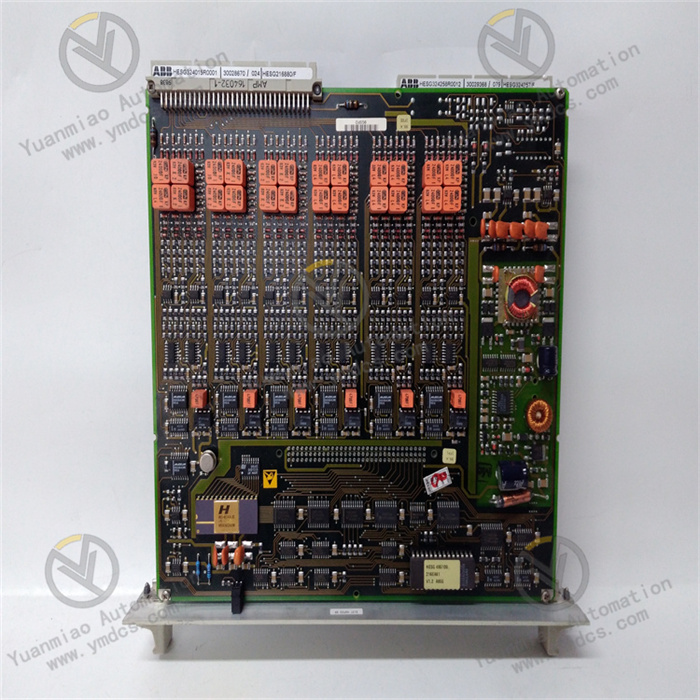
- Relay Outputs: 16 relays for controlling external devices.
- Digital Control Inputs: 12 inputs, compatible with 24V or 48V.
- Analog Outputs: 3 outputs, range ±10V.
- Analog Inputs: 3 inputs, supporting ±10V or ±20mA ranges.
- Temperature Sensor Interfaces: 3 interfaces for PT100 or PTC temperature sensors.
- Isolated Bending Machine Relay Interface: For connecting to bending machine relays.
- RS485 Interface: For communication with other devices.
- Optical Module Interface: Supports 3 optical links for data transmission.
- System Control Indicators: 4 indicators for monitoring system status.
- Independent Watchdog Function: Ensures system reliability.
- Operating Temperature Range: -25°C to +70°C, adaptable to various industrial environments.
Highlights
- Redundancy Support: Allows redundant configuration of all system interfaces using two PC D235 A devices to enhance system reliability and stability.
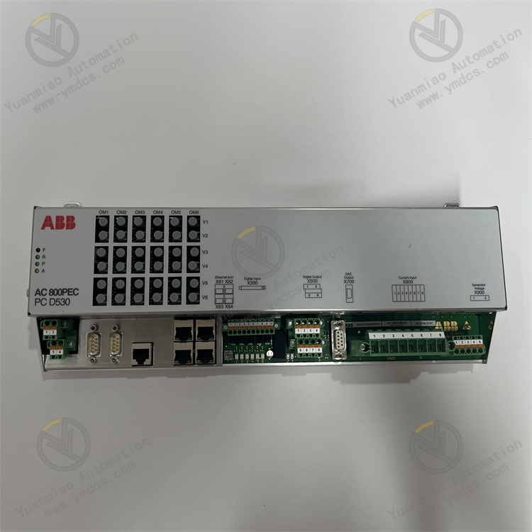
- Control Platform: Built on the AC 800PEC control platform, offering robust performance.
- Processing Module: FPGA-based control module for efficient processing.
- Rich Configuration: Equipped with a power supply (KU D210 A) and optical module (UF D202 A), with redundant 24V power input to ensure continuous operation.
Operation Guide for ABB PCD235A101 3BHE032025R0101
1. Pre-Installation Preparation
- Equipment Inspection: Thoroughly inspect the controller and its accessories to ensure completeness and no damage. Verify that the model, specifications, and serial number match the order.
- Document Review: Carefully study ABB's installation manual, user guide, and technical specifications to familiarize yourself with the controller's functions, performance parameters, and installation requirements.
- Environmental Preparation: Ensure the installation environment meets the controller's operational requirements for temperature, humidity, and electromagnetic interference. Prepare necessary installation tools and materials, such as screwdrivers, wrenches, and terminal blocks.
2. Installation Steps
- Location Selection: Choose a stable, vibration-free location that is easily accessible, with sufficient space reserved for maintenance and heat dissipation.
- Fixed Installation: Securely mount the controller in the predetermined location using appropriate mounting brackets or screws.
- Wiring Connections: Correctly connect power, signal, and control cables according to the wiring diagram and technical documents, ensuring firm connections to prevent looseness or short circuits.
- Communication Interface Configuration: Configure communication interfaces (e.g., Ethernet, serial communication) as per system requirements, and ensure communication parameters (e.g., baud rate, address) match other devices in the system.
3. Commissioning Steps
- Power Test: Use a multimeter to check if the power voltage meets requirements before switching on the power. After powering up, observe the indicator lights and display to confirm normal power supply.
- Function Test: Test all functions such as excitation current regulation and PID control according to technical documentation to ensure the controller correctly responds to input signals and outputs corresponding control signals.
- Communication Test: Perform communication tests with other devices via the configured communication interface to ensure normal data transmission.
- System Integration Test: Connect the controller to the entire power system for integration testing, observing its operational status to ensure system stability and compliance with design requirements.

Common Faults and Troubleshooting Methods
1. Communication Failures
- Symptom: The module cannot communicate normally with other devices, such as being unable to upload data or receive commands.
- Possible Causes and Solutions:
- Poor communication line connection: Check if communication cables are properly plugged in, and inspect for damage, breaks, or short circuits. Replug or replace cables if issues are found.
- Incorrect communication parameter settings: Verify that the module's communication parameters (e.g., baud rate, data bits, stop bits, parity) match those of other connected devices, and reconfigure if Inconsistency.
- Damaged communication interface: Check for physical damage to the interface (e.g., bent or broken pins). If damaged, replace the module or repair the interface.
2. Abnormal Excitation Current Control
- Symptom: Excitation current cannot stabilize at the set value, or overcurrent/undercurrent occurs.
- Possible Causes and Solutions:
- Faulty current sensor: Check if the current sensor is working properly by measuring its output signal. Replace the sensor if faulty.
- Improper PID parameter settings: Readjust PID parameters to achieve stable current control. Start with default parameters and fine-tune based on actual conditions.
- Faulty power unit: Check the power unit's output for normal operation and signs of component damage or overheating. Repair or replace the power unit if necessary.
3. Abnormal Voltage Monitoring
- Symptom: Monitored excitation voltage does not match the actual value, or overvoltage/undervoltage alarms occur.
- Possible Causes and Solutions:
- Faulty voltage sensor: Inspect the voltage sensor using methods similar to current sensor checks, and replace if problematic.
- Abnormal input power voltage: Check if the power voltage input to the module is stable and within the rated range. If unstable, inspect the power supply line and equipment.
- Faulty internal voltage measurement circuit: Requires professional maintenance to repair or replace faulty circuit components.
4. Module Overheating
- Symptom: Excessively high module surface temperature, possibly triggering overheat protection.
- Possible Causes and Solutions:
- Poor heat dissipation: Check if the module's cooling fan is operating normally and if heat dissipation channels are blocked. Clean the channels if blocked; replace the fan if faulty.
- Excessive load: Verify if the excitation system's load exceeds the module's rated capacity. If so, consider reducing the load or upgrading to a higher-capacity module.
- Faulty internal components: Short-circuited components or degraded performance may cause overheating, requiring professional detection and repair.