Description
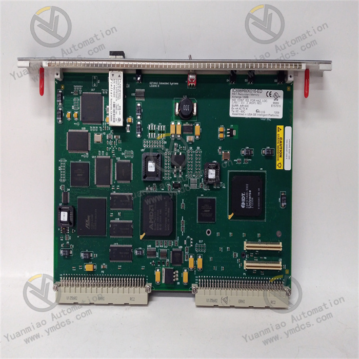
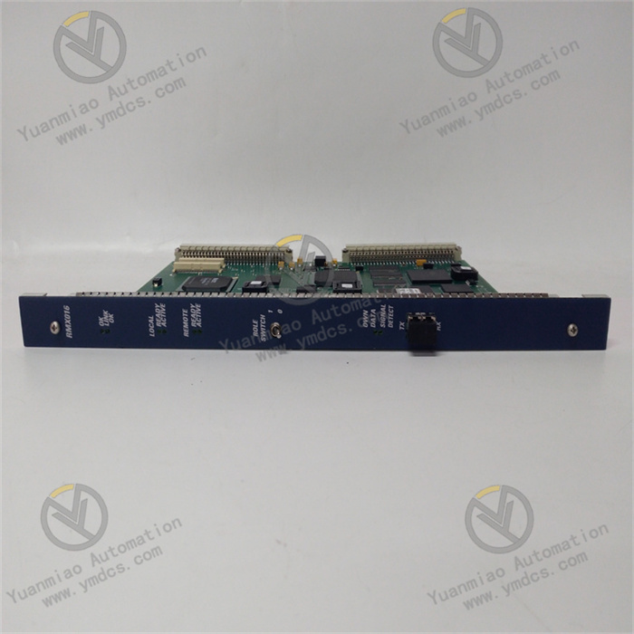
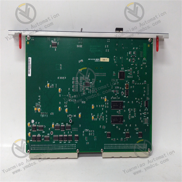
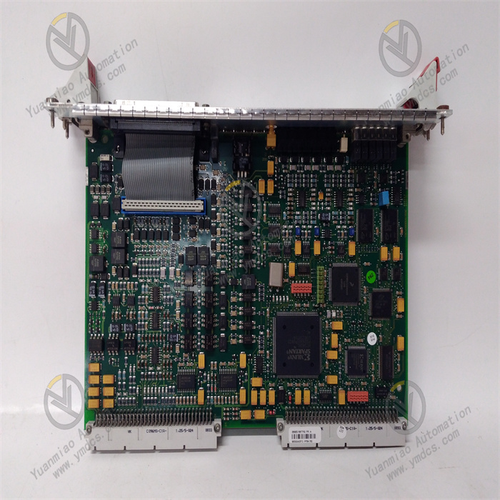
GE Fanuc IC698RMX016
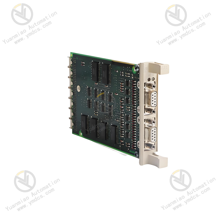
GE Fanuc IC698RMX016 is a redundant memory exchange module applied in the field of industrial automation, belonging to the RX7i PACSystems series.
Functional Purposes
- It can serve as a node on the reflective memory network or a specific link connecting two CPUs in a redundant system, used to determine the data sharing volume between PLCs and other computing devices, and realize data transmission between redundant CPUs.
Technical Parameters
- Memory Capacity: Equipped with 16MB of SDRAM user memory.
- Network Speed: The fiber optic network speed is 2.12Gbaud, and the transmission rate reaches 2.1GB/s.
- Operating Voltage: The working voltage is +5V DC, and the current requirement is 1.8A.
- Interface Type: Adopts fiber optic LC-type connectors, compliant with IEC 61754-20 standard, with zirconia ceramic ferrules, maximum insertion loss of 0.35dB, and return loss of -30dB.
- Operating Temperature: The working temperature range is between -20°C and +85°C.
Installation Requirements
- It needs to be installed in RX7i Rack 0 (main rack), and it is recommended to install it in slots 4 and 3 of the main rack, although it is not mandatory. During installation, first turn off the rack power, insert the module into the configured slot in the system, tighten the panel screws, then connect the fiber optic cable, and finally power on.
Configuration Parameters
- It is in an unconfigured state when initially powered on, and its optical transmitter is disabled. In reflective memory operations, users can choose to configure parameters such as redundant transmission mode, node ID, and network memory offset; if redundant link operation is selected, these parameters will be set by the CPU and cannot be configured by users.
How to Diagnose Faults in the IC698RMX016 Module?
I. Hardware Indicator Light Inspection
The IC698RMX016 module typically comes with the following indicator lights (subject to the actual product):
PWR (Power)
- Constant On: The module is normally powered.
- Off: Check whether the power input (+5V DC, 1.8A) is normal, whether the fuse is blown, and whether the power module is faulty.
- Flashing: Power fluctuation or abnormal internal power circuit of the module, requiring module replacement.
LINK (Link)
- Constant On: The fiber optic link is normally connected and communication is stable.
- Off:
- Check if the fiber optic connector is loose or contaminated (clean with anhydrous alcohol).
- Confirm that the fiber optic cable is not damaged, and test the light intensity with an optical power meter (the received light intensity should be between -18dBm and -3dBm).
- Check if the opposite-end device (such as another RMX016 or CPU) is working normally.
- Flashing: Packet loss or bit errors in the link, possibly due to aging of the fiber optic cable, interface mismatch, or electromagnetic interference.
ACTIVE (Activity)
- Constant On: The module is active and participates in reflective memory network communication.
- Off: The module is not correctly configured or has been disabled; check whether the node ID and network parameters in the software configuration are correct.
ERROR (Error)
- Constant On: The module detects internal faults (such as memory errors, clock abnormalities), requiring module replacement.
- Flashing: Intermittent errors (such as parity errors), and specific error codes can be viewed through the system log.
II. System Log and Software Diagnosis
View System Event Logs
- Read CPU logs through Cimplicity Machine Edition or PACSystems RX7i programming software to find error codes related to RMX016 (such as "Rogue Master", "Link Failure").
- Common error codes and their meanings:
- ERR_RMX_LINK_DOWN: Fiber optic link is disconnected.
- ERR_RMX_PARITY: Memory parity error, possibly due to module or fiber optic issues.
- ERR_RMX_CONFIG: Configuration parameters conflict with the network (such as duplicate node IDs).
Test Reflective Memory Communication
- Use the Reflective Memory Explorer tool provided by GE (needs to be installed separately):
- Check if all RMX016 modules are displayed in the node list.
- Test data read/write functions to verify whether memory areas can be accessed normally.
- Monitor network throughput and bit error rate; abnormal values (such as packet loss rate >1%) may indicate hardware faults.
Redundant Link Status Check
- If the module is used in a redundant system, confirm whether the primary and backup links switch normally:
- When the primary link is disconnected, the ACTIVE light should go off, and the backup link takes over communication.
- If the switch fails, check the redundant configuration parameters (such as "Redundancy Mode" setting).
III. Hardware Replacement and Isolation Testing
Fiber Optic Loop Test
- Temporarily disconnect the module and use an optical power meter to test the loop light intensity to ensure no abnormal attenuation (normal attenuation ≤3dB).
- Replace the fiber optic cable or connector to eliminate physical layer faults.
Module Replacement Method
- Swap the Suspected faulty RMX016 module with a known good module:
- If the fault shifts, it indicates that the original module is damaged.
- If the fault persists, check the slot power supply or backplane communication lines.
Single-Node Test
- In an offline environment, use two RMX016 modules to form a minimum system and test the communication function separately to exclude external interference.
IV. Common Fault Causes and Solutions
| Fault Phenomenon | Possible Causes | Solutions |
|---|---|---|
| No power indicator on the module | Abnormal power input, blown fuse, internal power failure of the module | Check the power voltage (+5V DC ±5%), replace the fuse or module |
| LINK light off | Loose/contaminated fiber optic connection, damaged cable, faulty optical transceiver | Clean the connector, replace the fiber optic cable, and test the light intensity with an optical power meter |
| ERROR light on constantly | Memory error, clock abnormality, firmware damage | Reset the module (power off and restart), and replace the module if invalid |
| "Rogue Master" displayed in system log | Multiple modules configured as master nodes (Node ID conflict) | Modify the software configuration to ensure only one master node in the network |
| Data transmission delay or packet loss | Aging of fiber optic cable, electromagnetic interference, module performance degradation | Replace the fiber optic cable, add shielding measures, and upgrade the module firmware |


