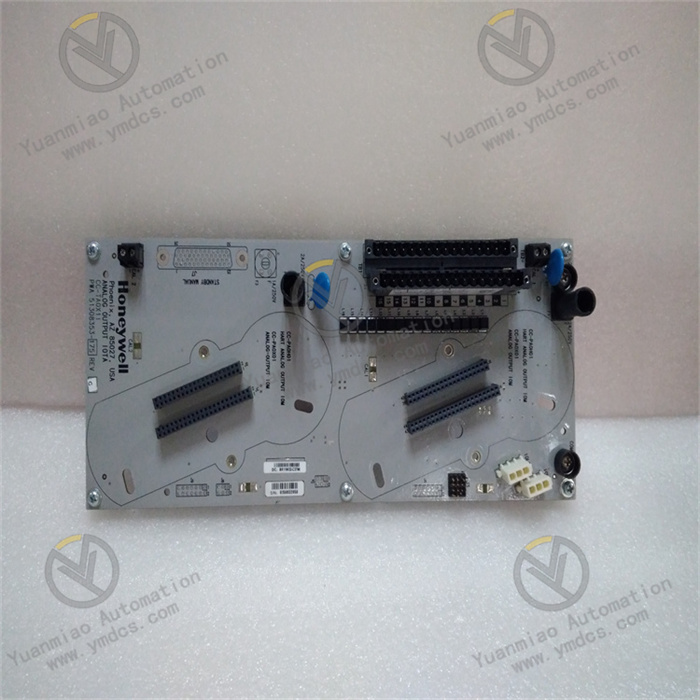
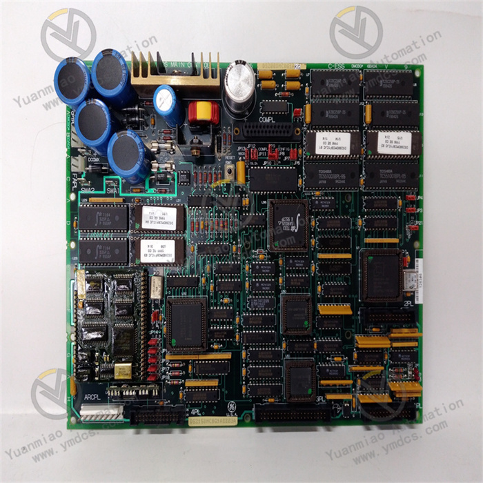
Description
Basic Information
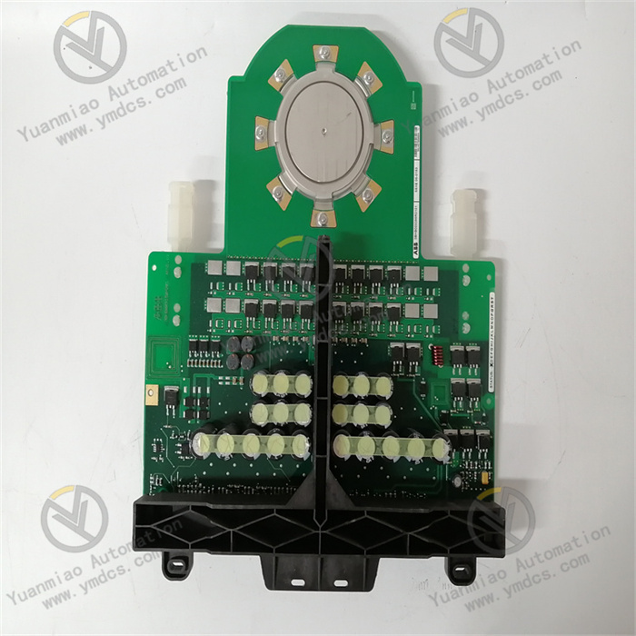
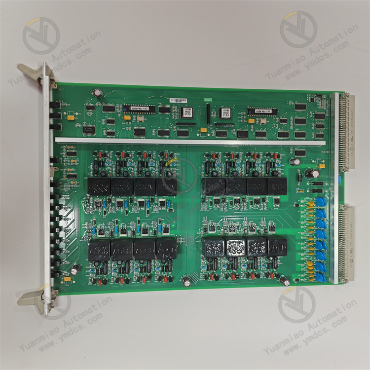
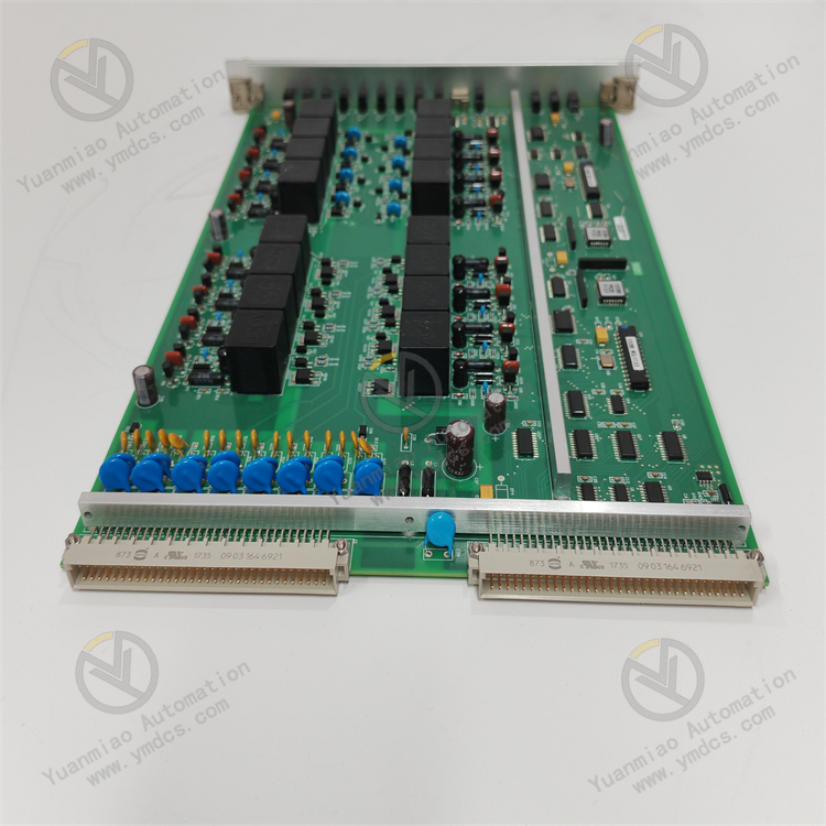
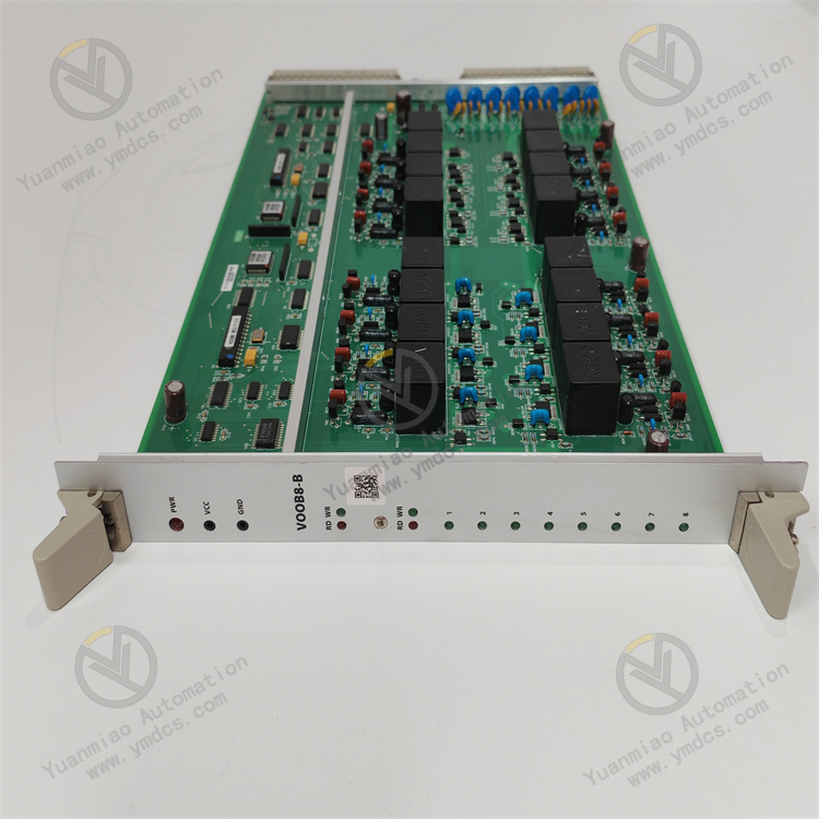
Model: ALSTOM VOOB8-B 12004-106-04
Version: V1.0.0
Input Voltage: 24V DC
Communication Protocols: Ethernet, Modbus
Operating Temperature Range: -20°C to 70°C
Dimensions: 150mm×100mm×50mm
Weight: 1.5kg
Model: ALSTOM VOOB8-B 12004-106-04
Version: V1.0.0
Input Voltage: 24V DC
Communication Protocols: Ethernet, Modbus
Operating Temperature Range: -20°C to 70°C
Dimensions: 150mm×100mm×50mm
Weight: 1.5kg
Product Features
- High Compatibility: Compatible with various PLC systems, ensuring easy integration into different automated control systems.
- Rugged Design: Constructed with durable materials and structures to withstand harsh industrial environments, such as high temperatures, humidity, and dust, adapting to diverse industrial site conditions.
- Multifunctional Applications: Supports various automation tasks, including data acquisition and control, and can be widely used in multiple industrial sectors such as manufacturing, logistics, and transportation.
- Energy Efficiency: Designed to reduce power consumption, helping lower operational costs in industrial applications.
- User-Friendly Interface: Features an intuitive interface that simplifies setup and monitoring, enabling operators to configure parameters and view device status with ease.
Application Areas
- Manufacturing: Used in automated assembly lines to achieve real-time monitoring of machine performance, reduce downtime through predictive maintenance practices, and improve production efficiency and product quality.
- Logistics: Applicable to automated inventory management systems for automated inbound/outbound management and inventory counting, enhancing the efficiency and accuracy of logistics operations.
- Transportation: Utilized in railway and traffic operations to optimize control systems, such as train operation control and signal control, ensuring the safety and efficiency of transportation.
Compiled based on general operation logic of industrial equipment and characteristics of similar products. For specific operations, refer to the equipment manual:
I. Installation and Connection
1. Pre-Installation Preparation
- Environmental Check: Ensure the installation location meets the operating temperature (-20°C to 70°C) and humidity (non-condensing) requirements, and is away from strong electromagnetic interference sources.
- Tool Preparation: Installation tools such as screwdrivers, multimeters, and network cables, as well as safety equipment such as protective gloves and goggles.
2. Physical Installation
- Mounting Method: Install on control cabinets or equipment racks via rear rails or screw holes, ensuring firm fixation to avoid vibration impacts.
- Dimension Reference: Reserve sufficient space according to the dimensions (150mm×100mm×50mm) for heat dissipation and subsequent maintenance.
3. Electrical Connections
- Power Connection:
- The input voltage is 24V DC. Confirm correct polarity (do not reverse positive and negative terminals) and use a multimeter to measure voltage stability.
- It is recommended to equip an independent power switch for emergency power-off operations.
- Communication Connection:
- Ethernet: Connect to an industrial switch or host computer via a network cable, supporting the Modbus TCP protocol. A fixed IP address needs to be configured.
- Modbus RTU: Connect using an RS485 interface, paying attention to terminating resistor configuration (typically 120Ω). Ensure communication parameters such as baud rate and parity check match those of the host computer.
- I/O Connection (if applicable): Connect peripheral devices such as sensors and actuators according to functional requirements, and label cables for easy troubleshooting.
II. Parameter Configuration and Initialization
1. Local Configuration (via Interface Operations)
- Operation Interface: Settings are made via the device's built-in LCD display or button menu (if available). Typical steps are as follows:
- Language Selection: Default is English, and Chinese can be switched if this function is available.
- Communication Parameters: Set Ethernet IP address, subnet mask, gateway, or Modbus slave address and baud rate (e.g., 9600bps).
- Functional Parameters: Configure data acquisition frequency, control logic thresholds (such as sensor trigger values), etc., according to the application scenario.
2. Remote Configuration (via Software)
- Host Computer Software: Use Alstom's dedicated configuration tools (such as Alstom Control Suite) or general Modbus debugging tools (such as Modbus Poll).
- Connection Steps:
- Ensure network connectivity between the device and the computer (Ethernet) or normal serial connection (RS485).
- Open the software, select the communication protocol and port, and establish a connection after entering the device address.
- Import or manually configure parameter templates and download them to the device to complete initialization.
III. Operation and Monitoring
1. Startup Operations
- Pre-Power Check: Confirm that all connections are secure, with no risk of short circuits or looseness.
- Startup Steps:
- Close the power switch. The device indicator lights (such as POWER and RUN) should light up normally (refer to the manual for indicator meanings).
- Wait for the self-check to complete (approximately 10-30 seconds), and the display will show "READY" or a similar status.
2. Status Monitoring
- Real-Time Data Viewing:
- Monitor input/output values, device operating temperature, communication status, etc., via the local interface or host computer software.
- Example: In a manufacturing scenario, real-time viewing of workpiece position or speed data collected by production line sensors.
- Alarm Notifications:
- E01: Communication timeout → Check network cable connection or Modbus slave address.
- E03: Low voltage → Measure whether the power input is stable at 24V DC±10%.
- In case of faults (such as communication interruptions or voltage anomalies), the device will issue alarms via indicator light flashing, interface pop-ups, or host computer notifications.
- Common alarm codes and handling:
IV. Routine Maintenance and Troubleshooting
1. Routine Maintenance
- Cleaning: Wipe the device surface with a dry soft cloth monthly to prevent dust accumulation from affecting heat dissipation.
- Connection Inspection: Check for loose wiring terminals quarterly, re-tighten them, and clean oxidation layers (if any).
- Functional Testing: Conduct a comprehensive functional test annually to verify the normality of data acquisition, control logic, and communication functions.
2. Common Faults and Solutions
| Fault Phenomenon | Possible Causes | Solutions |
|---|---|---|
| No power indication | Power not connected/fuse blown | Check the power switch and replace the fuse (if necessary). |
| Communication interruption | Damaged network cable/incorrect parameter configuration | Replace the network cable and reconfigure IP or Modbus parameters. |
| Abnormal data acquisition | Sensor failure/loose wiring | Replace the sensor and check wiring terminals. |
| No control output response | Actuator failure/logical parameter error | Test the actuator and correct control thresholds or logic flow. |
3. Advanced Maintenance
- Firmware Upgrade: Download the latest firmware via host computer software and upgrade it according to the prompted steps (note: do not power off during the upgrade).
- Module Replacement: If internal modules are damaged (such as the communication module), power off the device, remove the old module, install the new module, and reconfigure parameters (professional operation is recommended).

V. Safety Precautions
- Electrical Safety: Always power off before operation to avoid electric shock or equipment damage from live plugging/unplugging of cables or modules.
- Protection Requirements: In high-temperature, dusty, or humid environments, ensure the device casing is well-sealed and regularly inspect the protection level (such as IP rating).
- Data Backup: Regularly back up configuration parameters to prevent data loss due to equipment failure.
- Emergency Shutdown: If the device shows abnormal heating, smoking, or unusual noises, immediately cut off the power and contact technical support.