Description
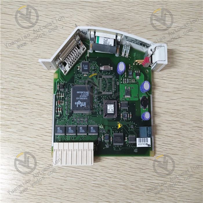
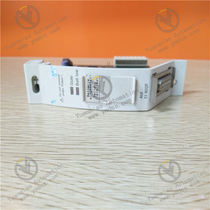
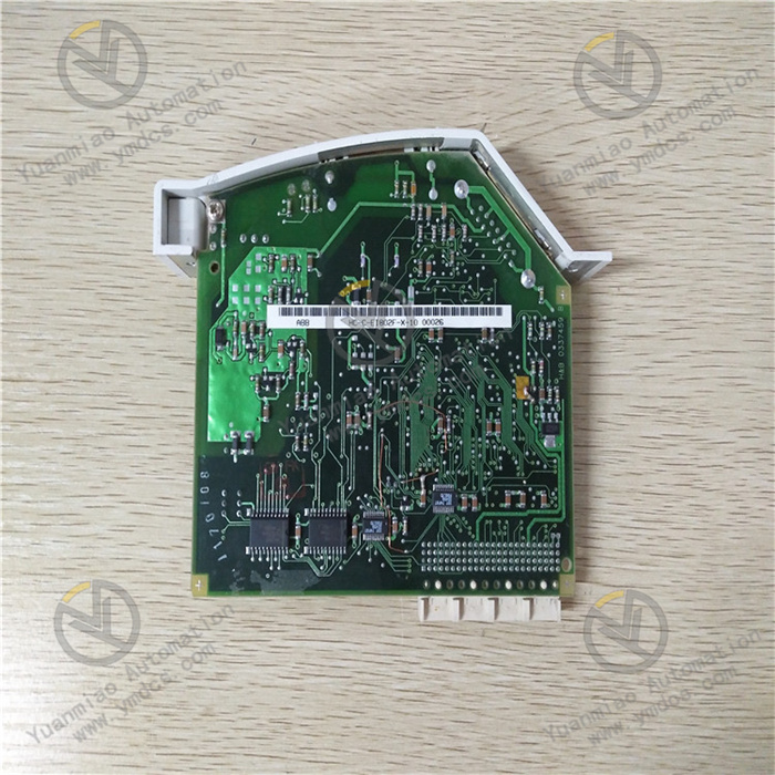
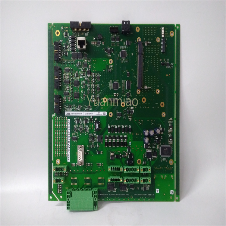
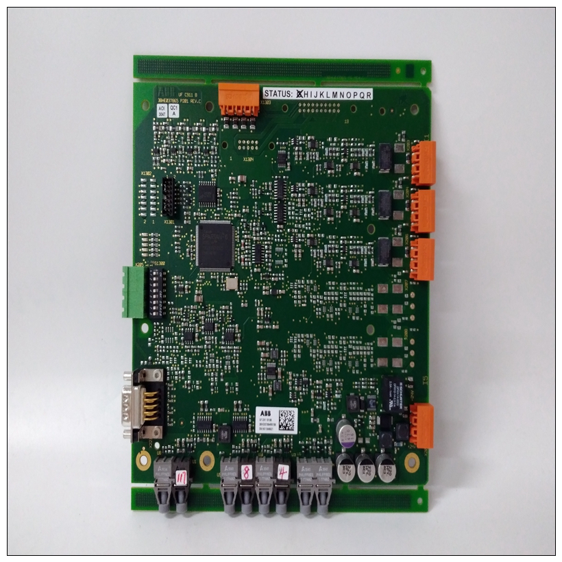
ABB EI802F 3BDH000016R1
I. Basic Information
Brand: ABB
Model: EI802F 3BDH000016R1
Type: Presumed to be a Digital Input Module (DI Module) (Note: In ABB's naming convention, "EI" typically denotes an input module. The "802" and "803" series may correspond to digital and analog types, respectively, subject to confirmation with the specific system).
Application Scenario: Suitable for distributed control systems (DCS) or PLC systems with controllers such as ABB AC 800M and AC 500-S, used for collecting digital signals from field devices (e.g., switch states, button signals).
II. Physical Characteristics
Dimensions: Approximately 120mm×80mm×35mm (compact design for industrial control cabinet installation).
Weight: Approximately 0.15-0.2kg (lightweight design).
Mounting Method: Rail mounting (e.g., DIN rail), supporting hot-swapping (for some models).
Weight: Approximately 0.15-0.2kg (lightweight design).
Mounting Method: Rail mounting (e.g., DIN rail), supporting hot-swapping (for some models).
III. Electrical Characteristics
Power Supply Voltage: 24V DC (industrial-standard power supply, supporting redundant power input).
Power Consumption: Approximately 1-2W (low-power design to reduce system energy consumption).
Number of Input Channels: Typically 16 channels (supporting multi-channel parallel acquisition; the exact number should be verified in the official manual).
Input Signal Types:
Power Consumption: Approximately 1-2W (low-power design to reduce system energy consumption).
Number of Input Channels: Typically 16 channels (supporting multi-channel parallel acquisition; the exact number should be verified in the official manual).
Input Signal Types:
- Dry contact signals (e.g., mechanical switches, relay contacts).
- Wet contact signals (e.g., 24V DC level signals, ON/OFF states).
Electrical Isolation: Isolation between channels or groups (prevents signal interference and improves noise resistance).
IV. Environmental Requirements
Operating Temperature: -25°C ~ +60°C (industrial-wide temperature design for harsh environments).
Storage Temperature: -40°C ~ +85°C.
Relative Humidity: 5% ~ 95% (non-condensing), with strong resistance to moisture and dust.
Protection Level: IP20 (requires installation in a control cabinet, dust-proof and splash-resistant).
Storage Temperature: -40°C ~ +85°C.
Relative Humidity: 5% ~ 95% (non-condensing), with strong resistance to moisture and dust.
Protection Level: IP20 (requires installation in a control cabinet, dust-proof and splash-resistant).
V. Communication Functions
Communication Protocols:
- Supports ABB's proprietary bus protocols (e.g., FIELDBUS) for seamless communication with AC 800M/AC 500-S controllers.
- Compatible with fieldbuses such as Profibus DP or Ethernet/IP (subject to system configuration).
Data Transmission: Real-time conversion of digital signals (0/1 states) into binary data, transmitted to the controller CPU via the backplane bus.
Diagnostic Functions: Supports channel status diagnosis (e.g., signal validity), open-circuit detection, power failure alarms, etc.
VI. Working Principle
Signal Acquisition
Receives switching signals from field devices (e.g., button presses, limit switch triggers) and connects to the module via input terminals (e.g., TB series terminal modules).
Receives switching signals from field devices (e.g., button presses, limit switch triggers) and connects to the module via input terminals (e.g., TB series terminal modules).
- Signal Conditioning: Filters input signals (eliminates high-frequency noise) and performs level conversion (matches internal module circuits).
Electrical Isolation
Isolates input signals from internal module circuits via optocouplers or relays to prevent external interference or overvoltage damage.
Isolates input signals from internal module circuits via optocouplers or relays to prevent external interference or overvoltage damage.
Analog-to-Digital Conversion (Digital signals require no analog conversion but need encoding)
Converts ON/OFF states of input signals into binary numbers (e.g., "1" for conduction, "0" for disconnection), stored in module registers.
Converts ON/OFF states of input signals into binary numbers (e.g., "1" for conduction, "0" for disconnection), stored in module registers.
Data Communication
Transmits binary data to the controller via the module's internal bus, where the controller executes corresponding actions (e.g., alarms, interlock controls) based on logic programs.
Transmits binary data to the controller via the module's internal bus, where the controller executes corresponding actions (e.g., alarms, interlock controls) based on logic programs.
Self-Test and Alarm
Regularly detects channel status, power voltage, and communication links. In case of faults (e.g., channel damage, communication interruptions), alarms via LED indicators and sends fault codes to the system.
Regularly detects channel status, power voltage, and communication links. In case of faults (e.g., channel damage, communication interruptions), alarms via LED indicators and sends fault codes to the system.
VII. Typical Application Scenarios
- Industrial Automation: Monitoring start/stop status of production line equipment, detecting safety door switches, and collecting sensor signals (e.g., proximity switches, photoelectric switches).
- Power Systems: Feedback on the position status of circuit breakers and disconnectors.
- Process Control: Real-time monitoring of valve switch states and motor operating status.
- Mechanical Engineering: Machine tool limit protection, robot IO signal interaction.
VIII. Common Faults and Causes
Power-Related Faults
- No Power to Module: Loose power connections, faulty power adapters, or blown internal fuses.
- Abnormal Power Indicator: Unstable voltage, aged filter capacitors, or damaged power chips.
Communication-Related Faults
- Unable to Communicate with Controller: Bus cable faults, address setting conflicts, or burned communication interface chips.
- Data Transmission Errors: Electromagnetic interference (e.g., improper wiring near frequency converters), protocol configuration errors (e.g., baud rate mismatches).
Input Channel Faults
- No Signal Response: Damaged external switches, loose terminal connections, or failed internal optocouplers in channels.
- False Signal Reports: Signal interference (unshielded cables or poor grounding), channel leakage (unstable voltage due to component aging).
Hardware Physical Faults
- Module Overheating: Inadequate ventilation in the installation environment, internal component short circuits (e.g., chip breakdown).
- Physical Damage: Terminal detachment due to mechanical vibration, circuit board corrosion (humid or corrosive environments).


