Description
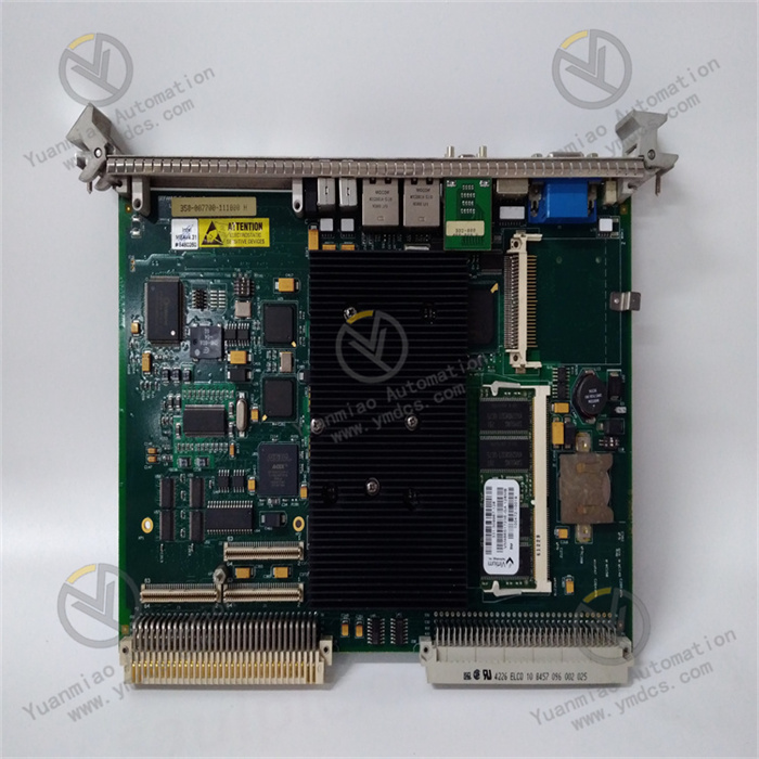
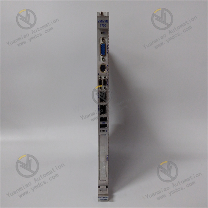
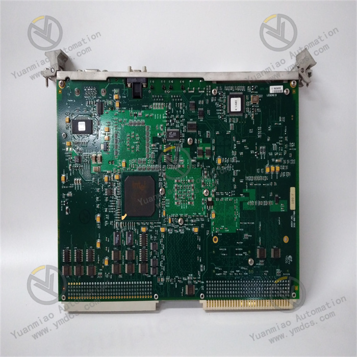
VMIVME-7700 350-007700-111000 H
I. Overview
The Abaco Systems VMIVME-7700 350-007700-111000 H is a 6U single-slot VMEbus Single-Board Computer (SBC) that has played a vital role in complex fields such as industrial automation, data acquisition, and communication since its launch. With its unique design and reliable performance, the product has earned a good reputation in the industry. Although it entered the Restricted Production Phase (RPP) since September 1, 2010, it still holds a certain application share in the market due to its own advantages. Based on the mature VME (VersaModule Eurocard) bus architecture and adopting a modular design, it features excellent stability and expandability, meeting the rigorous requirements of different industries for high-performance computing and data processing.
II. Functional Features
(1) Low-Power High-Performance Processor
Equipped with an Intel Ultra-Low Voltage Celeron processor, it offers optional operating frequencies of 400 MHz or 650 MHz, working in conjunction with the Intel 815E chipset at a stable 100 MHz front-side bus speed. This combination ensures low power consumption while providing reliable computing capabilities, efficiently handling various complex control algorithms and data processing tasks—whether real-time data analysis in industrial automation scenarios or massive data operations in communication systems—to lay a solid foundation for efficient system operation.
(2) Sufficient Storage and Memory Configuration
Featuring up to 512 MB of 100 MHz SDRAM, it provides ample space for system operation and temporary data storage, ensuring the system remains efficient and stable during multi-task parallel processing or large-scale data handling, avoiding lag or data loss caused by insufficient memory. Additionally, the auxiliary IDE interface can be equipped with up to 1 GB of bootable flash memory (optional) for storing system programs and critical data, safeguarding data integrity and fast reading during device startup and operation.
(3) Rich Timing and Storage Functions
Equipped with two 16-bit and two 32-bit programmable timers, it provides precise timing control for the system, meeting the needs of various scenarios such as timed operations in industrial automation production processes and sampling interval control in data acquisition. Meanwhile, the onboard 32 KB non-volatile SRAM can store key configuration information or save important data during system power failure, preventing data loss and enhancing device operation reliability and data security.
(4) Flexible Expansion Capability
With a PMC expansion site, users can flexibly insert PMC modules with various functions according to actual application needs—such as adding specific communication interfaces or data acquisition function modules—greatly enhancing the device's versatility and adaptability to better meet diverse functional expansion requirements in different application scenarios.
(5) Advanced Bus Compatibility
Fully compliant with the VMEbus Specification Rev. C.1 and featuring a transparent PCI-to-VMEbus bridge, this design allows the board to serve as both a system controller (coordinating and managing overall system operation) and a peripheral CPU (focused on specific task processing) in multi-CPU systems, facilitating the construction of complex multi-processor systems and effectively improving overall system performance and architectural flexibility.
III. Working Principle
(1) System Startup and Initialization
When the VMIVME-7700 350-007700-111000 H is connected to the VMEbus system and powered on, the onboard power management circuit first converts, stabilizes, and filters the input power to provide stable and adaptive working voltages for internal components (e.g., processor, memory, various interface circuits). Subsequently, the system initiates the initialization process: the processor reads startup code from the auxiliary IDE interface's bootable flash memory (if configured) or other specified boot devices, loads the operating system kernel and related drivers, and detects/configures hardware resources (including memory initialization, timer setup, I/O interface initialization), ensuring all components are in normal working condition for subsequent data processing and task execution.
(2) Data Processing Flow
During data processing, when the system receives external data processing task instructions, the Intel Ultra-Low Voltage Celeron processor parses and computes the tasks according to preset programs and algorithms. The processor uses its computing power to quickly handle complex logical operations and data manipulations—for example, analyzing massive real-time data collected by sensors in industrial automation control to determine production equipment status and generating corresponding control instructions based on the analysis. During computation, the processor frequently interacts with the onboard SDRAM, reading required data from memory and storing operation results back in memory in a timely manner, ensuring data processing continuity and efficiency through this high-speed interaction to enable the system to quickly respond to user tasks.
(3) Data Transmission Mechanism
The device transmits data with external devices via the VMEbus. When communicating with other VMEbus devices, data is orderly transmitted between devices through address lines, data lines, and control lines under the VMEbus protocol. For onboard I/O interfaces (e.g., USB interfaces connecting external devices), data first undergoes protocol conversion and buffering via the USB controller, then interacts with the processor or memory through the internal bus. If data transmission is performed via an extended PMC module, the PMC module converts data into a format suitable for VMEbus transmission based on its functional characteristics and interface protocol, then sends/receives data on the VMEbus. The entire process strictly follows relevant protocols to ensure data transmission accuracy and efficiency, enabling stable and reliable data communication between the device and the external environment.
IV. Operation Guide
(1) Pre-installation Preparations
- Compatibility Check: Before installation, carefully verify the detailed specifications of the target VMEbus system. Focus on key information such as VMEbus slot type, quantity, electrical characteristics, and available power to ensure full compatibility with the VMIVME-7700 350-007700-111000 H. Incompatible systems may cause installation failure or device damage, making compatibility confirmation a crucial step before installation.
- Tool Preparation: Prepare necessary installation tools (e.g., anti-static wristband, screwdrivers of suitable sizes). Wear an anti-static wristband during operation to prevent static electricity from damaging sensitive internal electronic components, ensuring installation safety.
(2) Module Installation
- Chassis Opening: Carefully open the VMEbus system chassis and locate a suitable 6U single-slot position inside for installing the VMIVME-7700 350-007700-111000 H module.
- Module Insertion: Hold the VMIVME-7700 350-007700-111000 H module, precisely align its bottom interface with the VMEbus slot, maintain verticality, and insert it smoothly and slowly into the slot. Avoid excessive force to prevent pin bending or damage, ensuring the module is fully seated and fixed.
- Module Fixing: Use a screwdriver to tighten the fixing screws on both sides of the module one by one, ensuring the module is firmly installed in the chassis without shaking, providing a solid physical guarantee for stable device operation.
(3) Device Connection
- Storage Device Connection (Optional): To connect an auxiliary IDE interface storage device (e.g., bootable flash memory), prepare corresponding data and power cables. Connect one end of the data cable to the device's auxiliary IDE interface and the other end to the storage device; meanwhile, correctly connect the power cable to the storage device to enable data storage and reading between the device and the storage device.
- Other Device Connections: Connect USB devices, etc., to the device's USB interfaces with appropriate cables per actual needs for data interaction with external devices. For PMC module expansion, insert the selected PMC module into the PMC expansion site in the correct orientation and manner, ensuring it is firmly fixed.
(4) System Startup and Operation
- System Startup: After completing all device connections, close the VMEbus system chassis and power on the system. Observe the device's indicator lights during startup; normally, the lights will turn on or flash in a specific sequence, indicating the device is performing self-checking and other startup processes.
- System Login and Operation: After startup, enter the correct username and password in the corresponding login interface based on the installed operating system. Upon successful login, use the device's functions for data processing, control operations, etc., via the OS or related applications—e.g., remotely monitoring and controlling production equipment through dedicated control software in industrial automation, or starting a data acquisition program to collect and store sensor data in data acquisition scenarios.
(5) Common Fault Troubleshooting
- Device Fails to Start: Check power connections for stability and confirm normal external power supply; inspect indicator light status. If lights are off or abnormal, the internal power module may be faulty, requiring professional maintenance. Meanwhile, verify that the boot device (e.g., auxiliary IDE flash memory) is properly connected and has intact data, as boot device issues may prevent normal system startup.
- Abnormal Data Transmission: For issues like data loss or slow transmission, check connection cables for damage and try reinserting or replacing them; confirm that interface drivers between the device and connected devices are correctly installed and up to date (download updates from the manufacturer's official website). For VMEbus data transmission, check the VMEbus system for faults or conflicts using relevant tools.
- Abnormal Expansion Module Function (if applicable): If a inserted PMC module fails to function, check for correct installation and secure fixing; confirm module-device compatibility and whether specific drivers need installation or configuration. If issues persist, contact the module supplier or Abaco Systems technical support for assistance.