Description
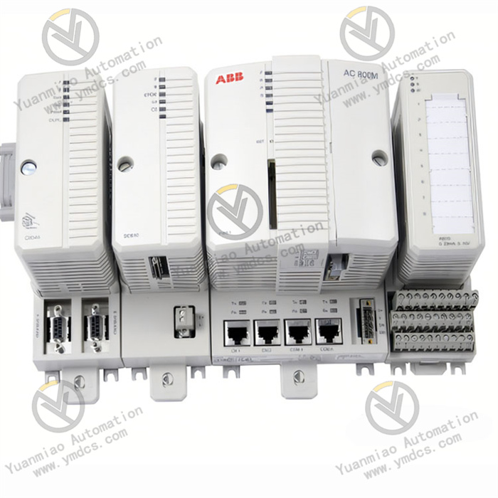
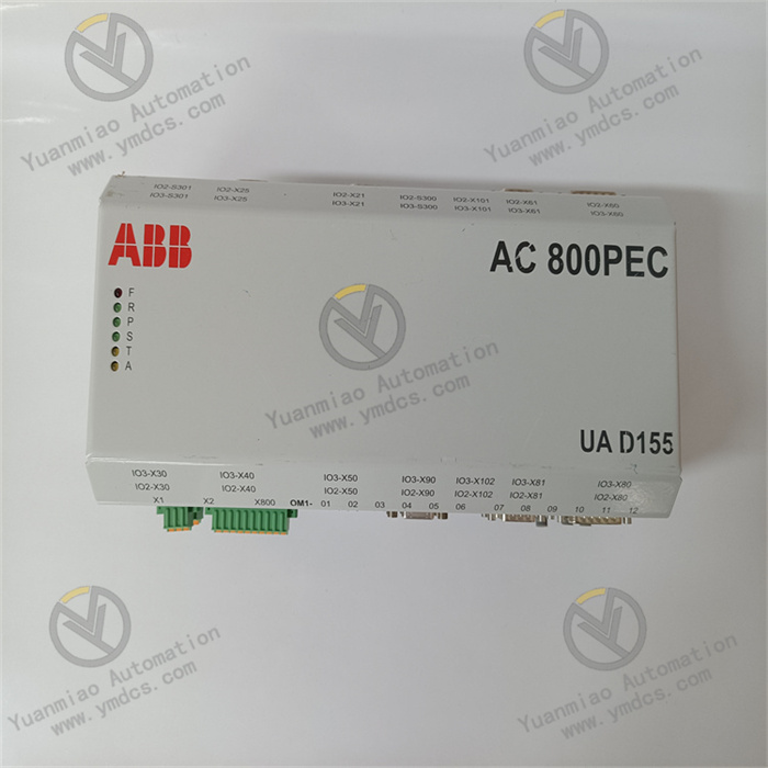
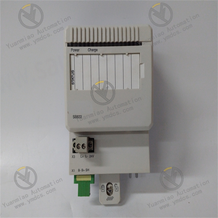
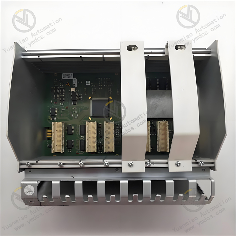
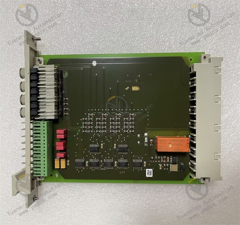
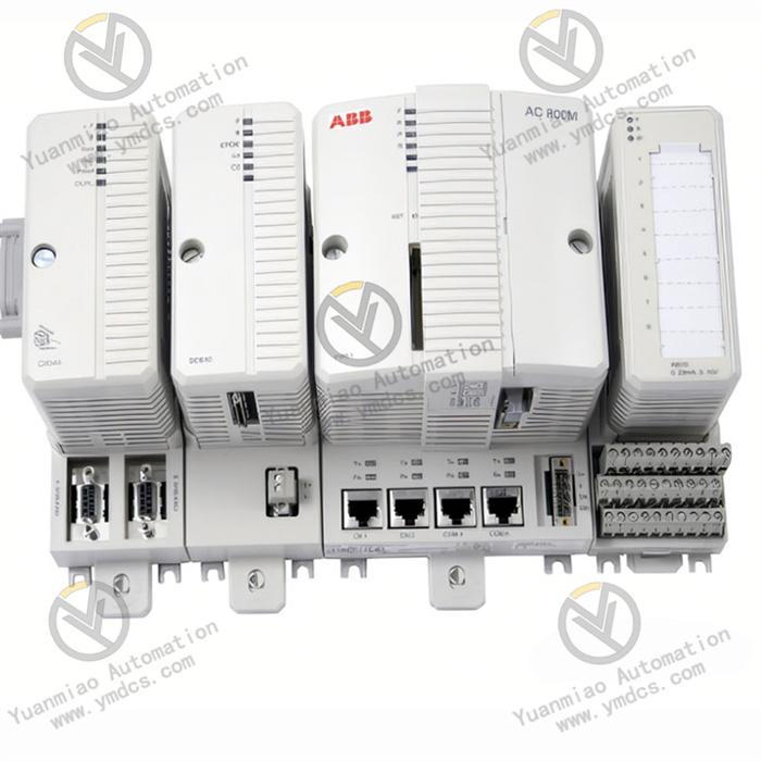
ABB PM851K01 3BSE018168R1
1. Basic Functions
Controller Core: As the core of an industrial control system, it is responsible for executing logic control, data processing, communication coordination, and other tasks.
Application Scenarios: Widely used in industrial scenarios requiring high-precision control and reliability, such as chemical, power, metallurgy, pharmaceutical, and food processing industries.
Performance Features:
Application Scenarios: Widely used in industrial scenarios requiring high-precision control and reliability, such as chemical, power, metallurgy, pharmaceutical, and food processing industries.
Performance Features:
- Supports multiple communication protocols (e.g., PROFIBUS, Ethernet/IP, etc.), enabling seamless connection with field devices and host systems.
- Features high reliability and redundancy capabilities (e.g., dual-controller hot standby), suitable for production environments with high continuity requirements.
- Supports modular expansion, allowing the construction of complex systems with I/O modules, communication modules, etc.
2. Technical Parameters
| Parameter | Description |
|---|---|
| Processor | 32-bit microprocessor, main frequency [specific value to be checked in the manual], supporting real-time operating system (RTOS). |
| Memory | Flash and RAM capacity (e.g., flash [X] MB, RAM [Y] MB, specific to the model). |
| Communication Interfaces | Standard Ethernet interface (e.g., 10/100 Mbps), serial ports (RS-232/485), supporting redundant communication configurations. |
| I/O Expansion | Connects to distributed I/O modules (e.g., DI/DO, AI/AO, etc.) via backplane bus, supporting a maximum of [X] modules. |
| Operating Voltage | DC 24 V (typical industrial-grade power supply), supporting a wide voltage input range. |
| Operating Temperature | -20°C ~ +60°C (adapting to temperature fluctuations in industrial environments). |
| Certifications | Complies with international standards (e.g., CE, UL, ATEX explosion-proof certification, etc., specific to application scenarios). |
Common Faults and Solutions for ABB PM851K01 3BSE018168R1
I. Power-Related Faults
1. No Power Supply to the Module (Power Indicator Off)
Possible Causes:
Possible Causes:
- External power supply not connected or unstable voltage (e.g., input voltage exceeding the module's rated range).
- Loose or poor contact in power terminals, or damaged cables.
- Faults in the module's internal power circuit (e.g., blown fuse, aged capacitor).
Solutions:
- Check if the power input meets the module's specifications (PM851K01 typically supports DC 24V power supply), and use a multimeter to measure voltage stability.
- Re-plug the power terminals to ensure secure connection, and replace damaged cables.
- If the internal fuse is blown, professional personnel must open the module for inspection and replacement (unauthorized operations may affect the warranty); if obvious physical damage such as a bulging capacitor is found, contact ABB for repair or module replacement.
2. Abnormal Power Indicator (Flashing or Steady On but Module Not Working)
Possible Causes:
Possible Causes:
- Excessive power ripple or electromagnetic interference (EMI).
- Faults in the module's internal power management chip.
Solutions:
- Add a filtering device (e.g., power filter) to the power circuit to ensure pure power supply.
- Check if the module is well-grounded and keep it away from strong electromagnetic devices (e.g., inverters, motors).
- If the abnormality persists after eliminating interference, it may be a hardware fault, requiring factory detection.
II. Communication-Related Faults
1. Failure to Communicate with Control Systems (e.g., PLC, Host Computer)
Possible Causes:
Possible Causes:
- Incorrect communication parameter settings (e.g., baud rate, protocol, IP address, station number, etc.).
- Damaged or loose communication cables (e.g., Ethernet, RS485) or interfaces.
- Hardware faults in the module's communication interface (e.g., burned network chip, solder joint detachment).
- Software compatibility issues (firmware version mismatch with the system).
Solutions:
- Verify with the module manual that communication parameters match the system (e.g., PM851K01 supports Modbus, Ethernet/IP, etc.).
- Replace communication cables and use an oscilloscope or cable tester to check signal transmission quality.
- Re-plug the communication interface and inspect for oxidation or physical damage; professional repair is required if the interface is damaged.
- Upgrade or downgrade the module's firmware to a compatible version (refer to ABB's official technical documentation and back up programs before operation).
2. Communication Interruption or Abnormal Data (e.g., Packet Loss, Bit Errors)
Possible Causes:
Possible Causes:
- Excessive communication network load (e.g., multiple devices sharing the bus, insufficient bandwidth).
- Signal distortion caused by electromagnetic interference.
- Module cache overflow or software logic errors.
Solutions:
- Optimize the network architecture, split the load, or upgrade communication media (e.g., use fiber optics instead of twisted-pair cables).
- Add shielding to communication cables and ensure reliable grounding, avoiding parallel routing with power cables.
- Restart the module or reset the communication driver, and check for unhandled communication errors in the program.
III. Abnormal Operating Status
1. Abnormal Module Indicator Status
Common Indicator Meanings (Taking AC 800M Series as an Example):
Common Indicator Meanings (Taking AC 800M Series as an Example):
| Indicator | Normal Status | Abnormal Status and Possible Causes |
|---|---|---|
| PWR (Power) | Steady on | Off: No power supply; Flashing: Power fault or module fault |
| RUN (Operation) | Periodic flashing | Steady on/Off: Abnormal program operation or system freeze |
| COM (Communication) | Flashing (data transmission) | Off: Communication interruption; Steady on: Communication anomaly |
| ERR (Error) | Off | Steady on/Flashing: Hardware fault, program error, or configuration error |
Solutions:
- Determine the fault type based on indicator combinations (e.g., steady ERR may indicate memory errors or I/O module faults).
- Try restarting the module (power off and wait for at least 10 seconds before powering on again). If the fault persists, check if configuration files are lost or corrupted.
- For program errors, use tools like ABB Control Builder for online diagnosis and download the correct program to the module.
2. Abnormal Program Operation (e.g., Logic Not Executing, Output Out of Control)
Possible Causes:
Possible Causes:
- Program logic errors (e.g., infinite loops, variable conflicts).
- Module memory faults or firmware defects.
- Abnormal communication between the I/O module and the main module, leading to data reading errors.
Solutions:
- Monitor program runtime via programming software to identify logic errors or breakpoints.
- Restore the module to factory settings (note: back up user programs) and re-download configurations.
- Check the firmness of I/O module connections and replace suspicious I/O modules or backplane bus adapters.
IV. Hardware Physical Faults
1. Module Overheating or Unusual Heat Generation
Possible Causes:
Possible Causes:
- Poor ventilation in the installation environment, blocked cooling vents.
- Damaged internal fan or detached heat sink.
- Abnormal power consumption due to component aging (e.g., chip short circuit).
Solutions:
- Ensure the module is installed in a well-ventilated control cabinet, away from heat sources, and clean dust from cooling vents.
- Check if the fan is operating normally and replace the damaged fan (if the module supports hot-swapping).
- If overheating is accompanied by unusual odors or smoke, power off immediately and contact professionals for maintenance to avoid expanding the fault.
2. Physical Damage to Interfaces (e.g., Broken Terminal Blocks, Deformed Sockets)
Possible Causes:
Possible Causes:
- External impact or excessive force during installation.
- Interface wear from frequent plugging and unplugging.
Solutions:
- Minor damage can be repaired (e.g., fixing terminals with conductive adhesive), while severe damage requires module replacement.
- Follow manual instructions during installation, use appropriate tools, and avoid violent operations.


