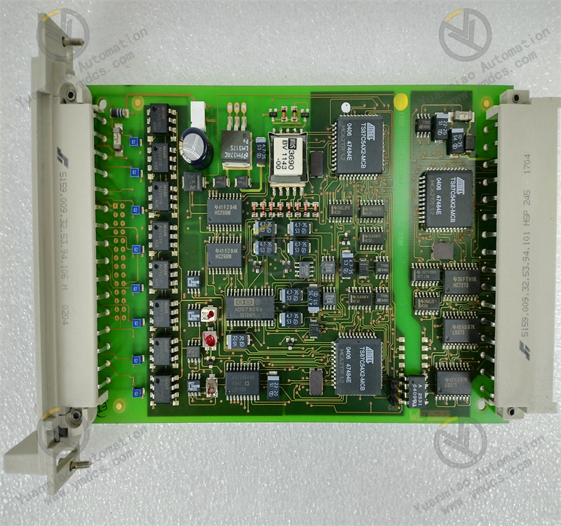
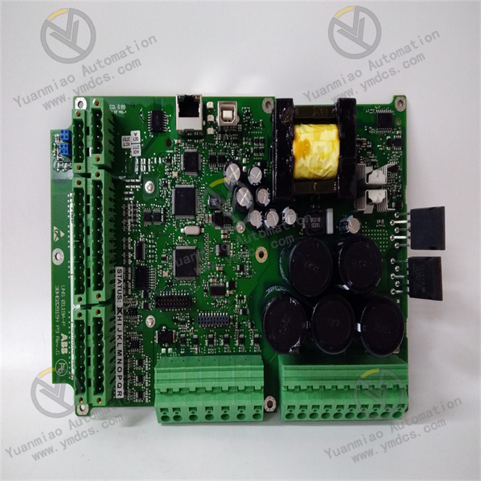
Description
The HIMA F3331 is an 8-channel safety-related digital output module with various features, suitable for a variety of industrial fields. Module Introduction Main Features: It has 8 relevant outputs, and both SIL2 and SIL3 versions are available. The output type is open collector, with short-circuit and surge protection functions. It is installed via DIN rail and is compatible with the Interbus-S protocol. Function and Purpose: It can be used to control related devices such as actuators, valves, and relays. The module automatically conducts tests during operation, including output signal readback, the ability to switch test signals, crosstalk tests, and line monitoring.
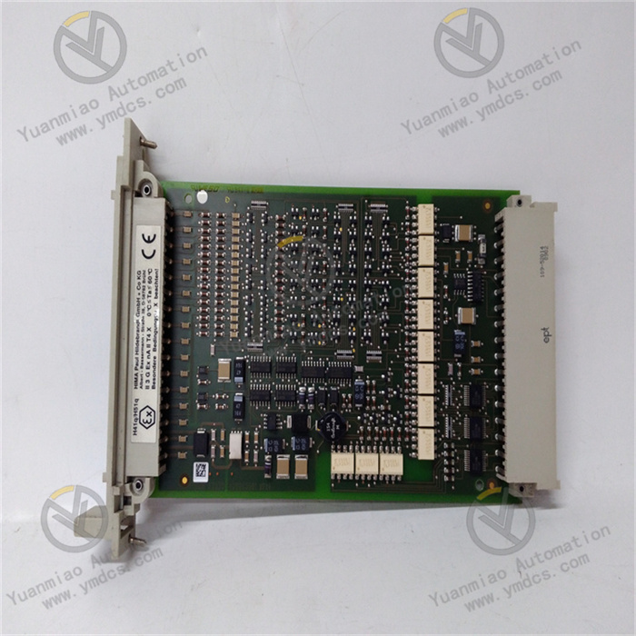
Technical Parameters: 1. Number of Channels: 8 channels. 2. Output Type: Digital output, open collector output, which can be used to control related devices such as actuators, valves, and relays. 3. Safety Level: Suitable for applications with safety requirements. Both SIL2 and SIL3 versions are available to meet the needs of different safety integrity levels. 4. Output Ratings: - Current Rating: 500mA per channel. It can withstand temporary short circuits, and the short-circuit current is 0.75 - 1.5A. - Voltage Rating: It is likely to be 24VDC (a typical value for similar modules). - Load Type: Resistive and inductive loads can reach 500mA (12W), and lamp loads can reach 4W. 5. Safety and Functional Features: It integrates safety shutdown functions, safety isolation, and line monitoring functions. When the L + power supply is interrupted, the output will not be activated. 6. Automatic Testing: The module automatically conducts tests during operation. The main test procedures include output signal readback (the working point of 0 signal readback ≤ 6.5V), the ability to switch test signals and crosstalk (walking bit test), and line monitoring. 7. Other Specifications: - Short-circuit Protection: The output can withstand a short-circuit current of up to 500mA. - Internal Voltage Drop: Under a 500mA load, the maximum is 2V. - Allowable Line Resistance (input + output): The maximum is 11 ohms. - Undervoltage Tripping: It is activated when ≤ 16V. - Output Leakage Current: The maximum is 350μA. - Maximum Output Voltage during Reset: 1.5V. - Watchdog Current Input: The maximum is 30mA. - Test Signal Duration: The maximum is 200μs.
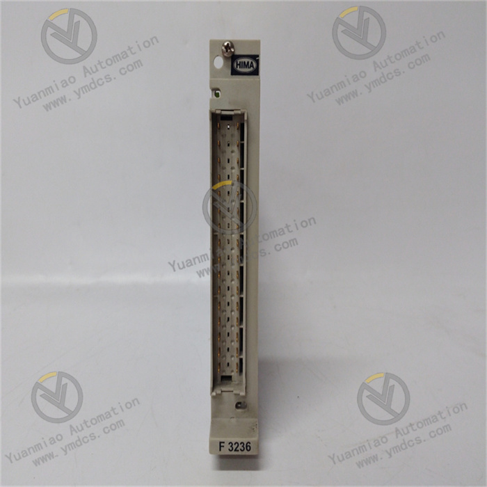
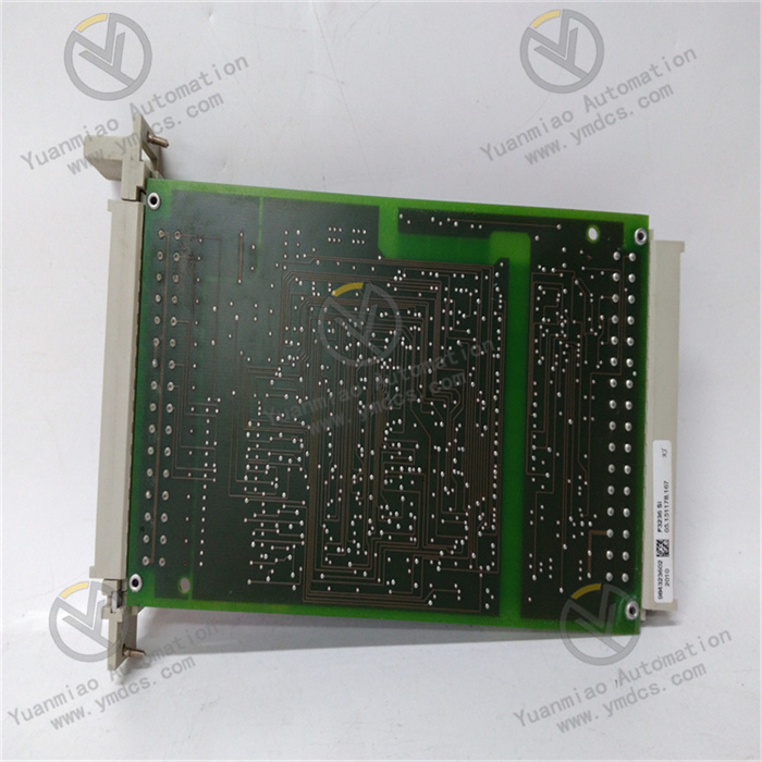
8. Space Requirements: 4TE (a standard unit in the rack system). 9. Power Consumption: 130mA at 5VDC and 180mA at 24VDC (additional load). 10. Electrical Connection: Electrical connections are usually achieved through appropriate terminal blocks to ensure reliable signal transmission and power supply. 11. Communication Protocol: It supports the Interbus-S fieldbus protocol and is compatible with various HIMA PLCs and other PLCs that support this protocol. 12. Mechanical Characteristics: - Installation Method: DIN rail installation, which is convenient for installation and removal in the control cabinet. - Dimensions: Approximately 100mm x 100mm x 40mm (there are slight differences in data from different sources, such as 4.7″x3.5″x1.8″). - Weight: Approximately 250g or 0.25lbs. 13. Environmental Parameters: - Operating Temperature Range: -20°C to +60°C or -25°C to +70°C (there are slight differences in data from different sources). - Storage Temperature Range: -40°C to +85°C. - Humidity Range: 5% to 95% RH, without condensation. - Protection Level: IP20, providing certain dust protection and limited protection against water splashes, suitable for a variety of indoor industrial environments.
Common Faults and Solutions 1. Abnormal Output Signal - Fault Phenomenon: The module's output signal cannot control external devices normally, such as the relay not operating, or the valve not opening or closing as expected. - Possible Reasons: Incorrect output wiring, faults in external devices, damage to the module's output channels, or the output signal being prohibited by software logic. - Solutions: Check whether the output wiring is correct, and ensure that the connection is firm and there are no short circuits or open circuits; check whether external devices are working properly, such as whether the relay coil is burned out or the valve actuator is faulty; try to replace the module's output channel. If the problem is solved, it indicates that the original channel is damaged, and the module needs to be repaired or replaced; check the relevant software logic to confirm whether there are conditions that prohibit the output signal, and adjust the logic according to the actual situation.
2. Short-circuit Fault - Fault Phenomenon: The module activates the short-circuit protection, resulting in the output failure, and there may be phenomena such as the module overheating and the fuse blowing. - Possible Reasons: Short circuits in external loads, short circuits caused by damaged insulation of the output line, or short circuits caused by faults in the internal circuit of the module. - Solutions: Check external load devices, such as actuators and relays, for short-circuit problems. If there are any, repair or replace the faulty devices; check the output line to see if there are situations such as line damage and insulation aging that cause short circuits. If so, replace the damaged line; if external causes are excluded, it may be a fault in the internal circuit of the module, and the module needs to be sent to a professional maintenance institution for repair.

3. Communication Fault
- Fault Phenomenon: The communication between the module and the PLC or other devices is interrupted, or there are errors in data transmission, resulting in the module being unable to receive control instructions or upload status information normally.
- Possible Reasons: Poor connection of the communication line, incorrect communication protocol settings, damage to the module's communication interface, or electromagnetic interference affecting communication.
- Solutions: Check the connection of the communication line to ensure that the plug and socket are in good contact and the line is not damaged or broken; confirm whether the module's communication protocol settings are consistent with those of the PLC or other devices, including parameters such as baud rate, data bits, stop bits, and parity bits. If there are errors, reset them; if the communication interface is suspected to be damaged, try to replace the module or send it for repair; check whether there are strong electromagnetic interference sources around. If so, take anti-interference measures such as shielding and filtering, such as using shielded cables and adding filters.
4. Module Overheating - Fault Phenomenon: The module overheats during operation, exceeding the normal working temperature range, which may lead to a decline in module performance or even cause faults. - Possible Reasons: Poor heat dissipation, the module operating under high load for a long time, or abnormal power consumption increase caused by internal component failures. - Solutions: Check the installation location of the module to ensure that there is enough space around for heat dissipation and avoid being blocked by other devices; check the working status of the module to see if there are situations such as long-term high-level output or large current output. If so, consider optimizing the control strategy to reduce the load of the module; if internal component failures are suspected, professional personnel need to conduct inspections and replace the damaged components.
5. Abnormal Indicator Lights - Fault Phenomenon: The indicator lights on the module do not light up, stay on constantly, or flash abnormally, and cannot correctly reflect the working status of the module. - Possible Reasons: Damage to the indicator lights, faults in the internal control circuit of the module, or incorrect indicator light status caused by software faults. - Solutions: If the indicator lights are damaged, try to replace them; for faults in the internal control circuit of the module, professional personnel need to conduct inspections; if it is a software fault, try to reset the module or re-download the configuration software to see if it can return to normal.