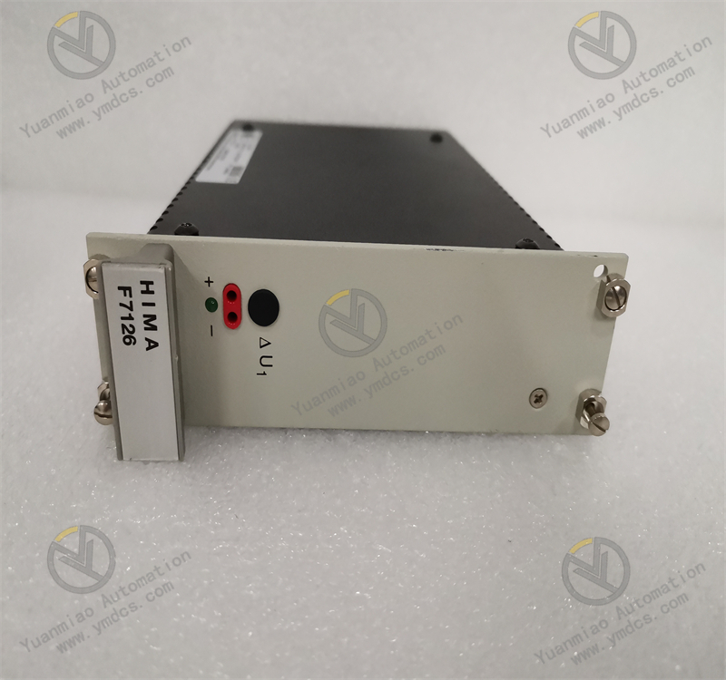
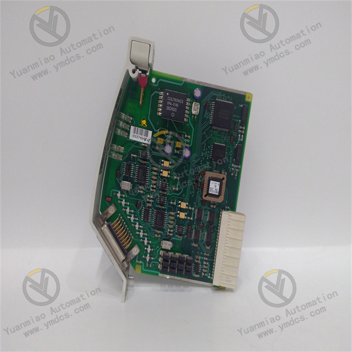
Description
ABB CI854BK01 3BSE069449R1
The CI854BK01 is a communication interface module for the ABB AC800M control system, serving as a PROFIBUS-DP/V1 interface. It is used to connect the AC800M controller with various field devices on the PROFIBUS-DP network, such as remote I/O, drives, low-voltage electrical equipment, and controllers, enabling efficient data transmission and communication between devices.
- Dimensions: 59mm (Width) × 185mm (Height) × 127.5mm (Depth).
- Weight: Approximately 700g (including the base).
- Installation Conditions:
- Operating temperature range: 0°C to 55°C.
- Storage temperature range: -40°C to 70°C.
- Humidity: 5% to 95% (non-condensing).
- Protection level: IP20, compliant with EN 60529 and IEC 529 standards.
Supports the PROFIBUS-DP/V1 protocol, a high-speed multi-purpose bus protocol with transmission rates ranging from 9.6 to 12000 kbit/s.
- The module includes two PROFIBUS ports to achieve line redundancy and supports PROFIBUS master redundancy, enhancing system reliability and stability.
- Master redundancy can be combined with CPU redundancy and CEX bus redundancy (BC810).
- Mounted on a 35mm DIN rail, it can directly connect to the S800 I/O system and other I/O systems, including all PROFIBUS DP/DP-V1 and FOUNDATION Fieldbus systems.
- Equipped with LED indicators to display power status, communication status, error alarms, etc., providing real-time feedback on the module's operating conditions.
- Standard Configuration: Includes the CI854 communication interface and TP854 base plate.
- Optional Accessories: May include PROFIBUS communication-related cables, terminal resistors, etc. (to be purchased separately).
Widely used in industrial automation fields such as power, manufacturing, chemical, and water treatment, it monitors, controls, and manages various industrial processes within ABB's automation systems (e.g., the 800xA system).
- Check power connections: Verify that the input voltage is within the normal range. If the voltage is abnormal, troubleshoot upstream power equipment or wiring faults. If the voltage is normal but the module is unresponsive, it may indicate an internal power circuit failure, requiring professional maintenance.
- Verify communication parameters: Ensure baud rate, address, etc., match the connected devices.
- Inspect PROFIBUS cables: Check for damage, looseness, or poor connections; replace or reconnect cables if necessary.
- Replace faulty components: If both cables and parameters are correct, the fault may lie in the module's or device's communication interface. Use the substitution method to identify and repair or replace the faulty device.
- Diagnostic information: Review the module's diagnostic data to determine the cause, such as software configuration errors, incompatible firmware, or hardware faults.
- Software errors: Redownload the correct configuration file.
- Firmware incompatibility: Update the module's firmware to the latest version.
- Hardware faults: Contact the manufacturer or professional maintenance personnel for repair.
- Preparation: Ensure the installation environment is free from high temperature, humidity, or strong electromagnetic interference. Prepare tools such as a screwdriver.
- Rail installation: Mount a 35mm DIN rail on the control cabinet or equipment frame, ensuring it is securely fixed.
- Module mounting: Align the CI854BK01 module's installation slide arms with the DIN rail and clip the module onto the rail. If using a base plate (e.g., TP854), install the base plate first, then mount the module.
- Electrical connections:
- Connect the module's interfaces to the processor unit and PROFIBUS-DP network devices as per the manual.
- Note: PROFIBUS DP must be terminated at both outermost nodes using connectors with built-in termination, ensuring connectors are inserted and powered.
- Installation check: Verify secure module mounting and reliable electrical connections, ensuring all wiring meets safety standards.
- Configuration tool preparation: Use ABB's engineering software, such as Control Builder M for AC800M control systems.
- Hardware configuration: Set up the module's position, slot number, and other parameters in the software according to the actual system architecture.
- Communication parameter configuration: Configure protocols, addresses, baud rates, etc., to match the connected devices (e.g., PROFIBUS-DP parameters).
- Functional configuration: Define data transmission modes, formats, monitoring, and diagnostic functions (e.g., periodic or on-demand data transmission, fault alarm triggers).
- Configuration download: Upload the configured file to the CI854BK01 module to activate the settings.
![]()