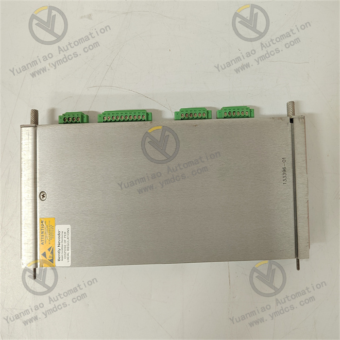
Description
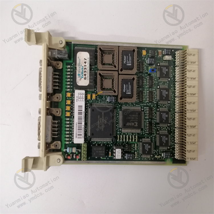
ABB 07KT97 GJR5253000R0200
I. Basic Information
- Full Model: 07KT97 GJR5253000R0200
- Series: ABB industrial automation control module, most likely belonging to digital input/output (DI/DO) modules. It is compatible with AC 500 series PLCs or similar control systems, and belongs to the same product series as the 07KT94 module.
- Purpose: As a signal processing unit in industrial automation systems, it connects devices such as switches, sensors, and actuators to achieve logical control and status feedback of discrete quantities, suitable for automation scenarios in manufacturing, energy, power, infrastructure, and other fields.
II. Core Functions and Features
1. Digital I/O Capability
- Channel Configuration: It is speculated to support 16 digital input (DI) channels or 16 digital output (DO) channels, or a mixed configuration (such as 8DI+8DO). The specific details shall be subject to the official manual.
- Signal Types:
- DI (Input): Compatible with dry contacts and wet contacts (such as 24V DC signals), and can be connected to mechanical switches, proximity sensors, photoelectric switches, etc.
- DO (Output): May be relay output (high load capacity) or transistor output (high-frequency response). The relay contact capacity is usually 2A/250V AC or 3A/30V DC, and the transistor output is about 24V DC/0.5A.
- Isolation Characteristics: Optocoupler or relay electrical isolation is adopted between channels, with an isolation voltage ≥500V AC to prevent interference from affecting system stability.
2. Electrical Characteristics and Protection
- Input Characteristics: The input voltage range for logic "1" is usually 15-30V DC (wet contact), with a response time ≤10ms and an input impedance ≥4.7kΩ.
- Output Characteristics:
- Relay Output: Supports inductive loads (such as solenoid valves and contactors), with a mechanical life ≥10⁶ operations, suitable for low-frequency and high-current scenarios.
- Transistor Output (if available): The response speed ≤1ms, suitable for high-frequency switching (such as pulse signal control), but the load capacity is low.
- Anti-Interference Design: Built-in filter circuit, in line with industrial-grade anti-electromagnetic interference (EMI) and radio-frequency interference (RFI) standards, adapting to harsh environments.
3. Diagnosis and Status Indication
- LED Indicators: Each channel is equipped with an independent status light (ON/OFF), and module-level indicators (PWR, FAULT) display the power and fault status, facilitating on-site maintenance.
- Fault Detection: Supports channel-level short-circuit and overload detection, automatically cutting off the output and triggering an alarm in case of faults to improve system safety.
III. Technical Parameters (Speculated, Referring to Similar Series Modules)
| Parameter Dimension | Specific Indicators (refer to 07KT94, and the actual ones shall be subject to the manual) |
|---|---|
| Number of Channels | 16 DI channels or 16 DO channels (may support mixed configuration) |
| Input Type | Dry contact/wet contact (24V DC), input impedance ≥4.7kΩ |
| Output Type | Relay output (2A/250V AC) or transistor output (24V DC/0.5A) |
| Response Time | DI≤10ms, DO (relay)≤10ms, DO (transistor)≤1ms |
| Operating Voltage | DC 24V (±10%), power consumption ≤5W |
| Operating Temperature | -20℃~+60℃, humidity 5%~95% (non-condensing) |
| Protection Level | Panel IP20 (installed in the control cabinet) |
IV. Application Scenarios
1. Manufacturing Automation
- Start/Stop Control of Production Line Equipment (such as machine tools and conveyor belts): Collect button signals through DI, and drive contactors or solenoid valves through DO.
- Equipment Status Monitoring: Read sensor signals (such as limit switches and encoders) in real time, and feedback them to the PLC for logical operations.
2. Energy and Power
- Switching Quantity Control in Substations: The DO output controls the opening and closing of circuit breakers, and the DI collects the status of auxiliary contacts to realize the automation of the power system.
- New Energy Power Generation (Wind Power, Photovoltaics): Monitor the operating status of equipment (such as the pitch position of wind turbines and the switching status of photovoltaic combiner boxes).
3. Infrastructure
- Building Automation: Timing control of the lighting system and monitoring of the elevator door status, realizing logical linkage through the DI/DO module.
- Water Treatment Plant: Start/stop control of pumps and valves (such as sewage lift pumps and sluice gates), realizing automatic start/stop combined with sensor signals.
V. Installation and Usage Key Points
1. Installation Method
- Adopt DIN rail installation, which needs to be matched with the AC 500 series rack or a compatible PLC system. The module spacing ≥15mm to ensure heat dissipation.
- The power wiring shall use wires with a cross-sectional area ≥1.5mm², and the grounding resistance ≤1Ω to avoid interference caused by poor grounding.
2. Wiring Specifications
- DI Input: Use shielded cables to reduce electromagnetic interference during long-distance transmission, and pay attention to the positive and negative polarity of wet contact input.
- DO Output: When driving inductive loads, the relay output needs to be connected in parallel with a freewheeling diode (such as 1N4007), and the transistor output needs to be connected in parallel with an RC snubber circuit to prevent back electromotive force from damaging the module.
3. Configuration and Programming
- Use ABB Automation Builder or Control Builder F software to configure parameters such as I/O addresses, input filter time, and output types.
- In the PLC program, read the DI status or control the DO output through bit operation instructions (such as LD, OUT, SET, RST).
4. Maintenance Notes
- Regularly check whether the terminal block is loose (it is recommended to tighten it once every six months) to avoid signal abnormalities caused by poor contact.
- If it is a relay output, the module needs to be replaced when the contact wear is serious (contact resistance >1Ω); the transistor output should avoid long-term overload.
- Some models support hot swapping, but when replacing, ensure that no critical tasks are running in the system to prevent control interruption.
VI. Comparison with Similar Products (Refer to the Comparison Logic of 07KT94)
| Parameter Dimension | ABB 07KT97 | Siemens S7-1200 SM1223 (Mixed Module) |
|---|---|---|
| Number of Channels | 16 channels (DI/DO optional) | 8DI+8DO (relay/transistor in separate models) |
| Output Type | Relay/transistor optional | Model-specific (relay or transistor) |
| Isolation Voltage | 500V AC | 500V AC |
| Applicable Systems | ABB AC 500 series | Siemens S7-1200 series |
| Response Speed | Relay≤10ms, transistor≤1ms | Relay≤10ms, transistor≤1ms |
VII. Typical Supporting Modules
- Controllers: ABB AC500 CPU (such as PM581, PM590), AC500-eCo CPU (economical controller).
- Power Module: PS511 (DC 24V power supply) provides stable power supply for I/O modules.
- Communication Modules: CM571 (Modbus RTU), CM572 (Profibus DP), CM582 (Ethernet IP) to realize communication with the upper computer or other devices.