Description
ABB BCU-02 3AXD50000006338
I. Overview
ABB BCU-02 3AXD50000006338 is a dedicated Basic Control Unit, with its core positioning as the "core module for local inverter control and I/O expansion". Serving as the connection bridge between the inverter and external control systems, this unit’s core functions include providing basic logic control, multi-speed setting, timed start/stop, fault reset, and I/O signal expansion for ACS800 inverters. It enables autonomous local operation of equipment without relying on an external PLC, and is widely applied in industrial machinery scenarios such as fans, water pumps, compressors, and conveyor belts. It is a cost-effective core component for simplifying control architectures and enhancing the independent operation capability of equipment in small and medium-sized automation systems.
II. Core Features
Deep Compatibility and Plug-and-Play with ACS800 Series: Specifically designed for ACS800 series inverters (e.g., cabinet-type/wall-mounted models like ACS800-01 and -04), it is directly installed in the inverter’s control card slot via a dedicated backplane interface. It enables high-speed communication with the main control board without additional wiring and can be put into operation immediately after parameter configuration, significantly reducing on-site installation and commissioning costs.
Basic Logic Control and Local Autonomy: Supports 8 preset multi-speed control, S-curve acceleration/deceleration adjustment, timed start/stop, and automatic fault reset logic. It can independently realize motor start/stop, direction switching, and process variable adjustment, eliminating the need for an external PLC. It meets the demand for simplified control architectures in small and medium-sized scenarios and reduces overall system investment.
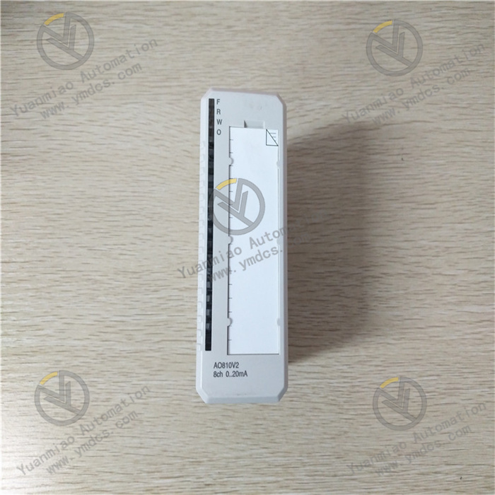
Rich I/O Configuration and Signal Expansion: Comes standard with 6 channels of 24VDC digital inputs (compatible with PNP/NPN), which can connect signals such as start/stop, fault alarm, and multi-speed selection; 2 channels of relay outputs (5A/250VAC, normally open/normally closed optional) for status indication or auxiliary equipment control; 1 channel of analog output (0-20mA/4-20mA) that can output process variables like frequency and current, adapting to on-site signal acquisition and control requirements.
Fault Data Management and Parameter Backup: Integrates an SDHC memory card slot for storing real-time inverter operation data and fault information, facilitating fault traceability and analysis by ABB service personnel; equipped with a removable memory unit, the memory unit can be directly transferred when replacing the control unit to retain original parameter settings, avoiding repeated configuration and improving operation and maintenance efficiency.
- Industrial-grade Reliability and Safety Interlock: Covers an operating temperature range of -10℃~50℃, with excellent electromagnetic interference resistance, meeting the 24/7 continuous operation requirements of industrial sites; supports interlock with external safety circuits, and can connect emergency stop button signals to trigger safe shutdown of the inverter, ensuring equipment operation safety relying on the inherent safety features of the ACS800.
III. Technical Parameters
| Parameter Name | Specification |
|---|---|
| Product Model | ABB BCU-02 3AXD50000006338 |
| Product Type | Dedicated Basic Control Unit for inverters, compatible with ACS800 series |
| Product Attribute | Compact PCB module, no independent CPU, relies on inverter main control board for collaborative operation, certified by CE and UL/cUL |
| Power Supply Parameters | Operating Voltage: External 24VDC, powered by inverter or external power supply |
| I/O Configuration | Digital Inputs: 6 channels of 24VDC (compatible with PNP/NPN); Relay Outputs: 2 channels (5A/250VAC); Analog Output: 1 channel (0-20mA/4-20mA) |
| Communication and Expansion | Communication Method: Communicates with ACS800 main control board via backplane interface; Expansion Slot: Supports connection of RDCO DDCS communication option board |
| Storage Function | Equipped with SDHC memory card slot (for fault data storage) and removable memory unit (for parameter backup) |
| Environmental Adaptability | Operating Temperature: -10℃~50℃; Protection Level: Adaptable to inverter cabinet protection (IP20 and above) |
| Compatibility and Adaptation | Exclusively compatible with ABB ACS800 series inverters (models such as ACS800-01 and -04), supports configuration via DriveWindow/DriveComposer software |
| Additional Functions | Built-in Real-Time Clock (RTC), 8-step multi-speed control, S-curve acceleration/deceleration, energy consumption statistics, fault self-diagnosis |
IV. Working Principle and Application Logic
The ABB BCU-02 3AXD50000006338 control unit realizes local control and signal expansion relying on the main control board of ACS800 inverters based on the collaborative working logic of "signal acquisition - logic coordination - control output - data storage". Its core working process is as follows:
The unit accesses external control signals (such as emergency stop button, multi-speed selection switch, liquid level/pressure sensor signals) through its built-in I/O interfaces, and establishes real-time communication with the main control board of ACS800 inverters via the backplane interface. It transmits external signals to the main control board and synchronously receives inverter operation status data fed back by the main control board.
Relying on the computing power of the main control board’s CPU, it performs logical operations on input signals according to preset parameters (multi-speed values, acceleration/deceleration time, timing rules, etc.), generates control commands such as motor start/stop, speed adjustment, and direction switching, and executes the S-curve acceleration/deceleration algorithm to reduce mechanical impact and protect equipment components.
Transmits the generated control commands to the inverter’s actuator to achieve precise motor control; at the same time, feeds back inverter operation status (running/fault) and process variables (frequency/current) to external devices such as indicator lights and recorders through relay output and analog output interfaces, realizing status visualization.