Description
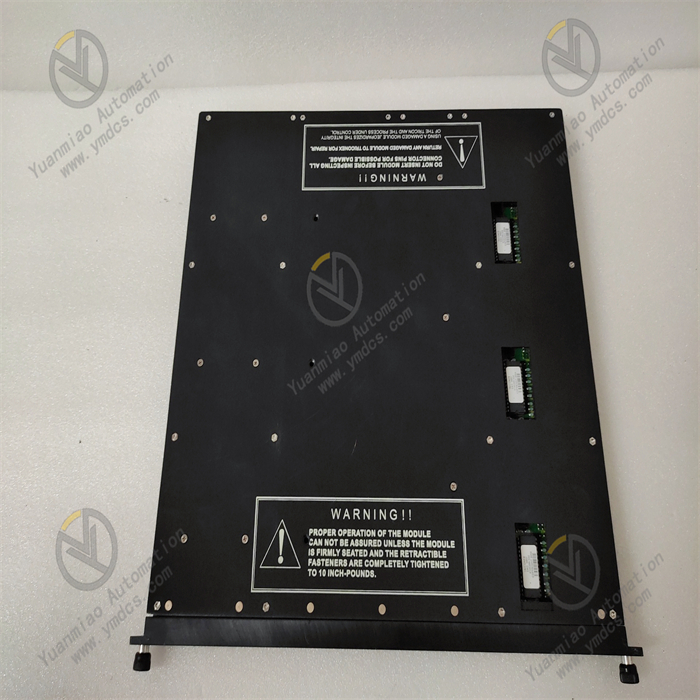
Triconex 3805E
The Triconex 3805E is an analog output module featuring a TMR (Triple Modular Redundancy) design and complying with IEC61508/61511 standards, ensuring high reliability and availability of the system. The module receives output signals from the main processor module on each of its three channels, then votes on each set of data and selects a healthy channel to drive the eight outputs. It monitors its own current output (as input voltage) and maintains an internal voltage reference for self-calibration and module health information.
Each channel is equipped with a current loop-back circuit to verify the accuracy and presence of analog signals independently of load presence or channel selection. The module is designed to prevent unselected channels from driving analog signals to the field and performs continuous diagnostics on each channel and circuit of the module. Any diagnostic failure will disable the faulty channel and activate a fault indicator, which in turn triggers a chassis alarm. The module can continue to operate normally even when up to two channels fail. Open-loop detection is provided by the LOAD indicator, which activates if the module cannot drive current to one or more outputs.
- Output Current Range: 4–20mA output (+6% overrange).
- Number of Output Points: 8 points.
- Isolation Characteristics: None, common return, DC coupling.
- Resolution: 12 bits.
- Output Accuracy: Within the 4–20mA range, ≤0.25% of full scale (0–21.2mA) at 0–60°C.
- Overrange Protection: +42.5VDC, continuous.
- Leg Fault Switching Time: Typically <10ms.
- TMR-Based Technology: Adopts a triple-redundant fault-tolerant design compliant with IEC61508/61511 standards. Each system channel independently executes control programs and operates in parallel with the other two channels. The hardware voting mechanism votes on and diagnoses field digital inputs/outputs, and processes analog inputs by median filtering, enhancing system reliability and availability. It can identify component faults and automatically exclude them, allowing online repair of faulty components without interrupting process operations.
- Multi-Function Integration: Capable of input signal reception, data processing, logical control, and output signal generation. It can integrate with various sensors, actuators, and other control devices to achieve automated control.
- Communication Capability: Equipped with communication interfaces to support data exchange with other devices and systems. It can integrate with host computers, monitoring systems, and networks to enable remote monitoring and control functions.
- Hot-Swap Function: Supports hot-swapping, allowing module replacement and maintenance during system operation without shutdown, reducing downtime and improving production efficiency.
- Petrochemical Industry: Used in critical applications such as safety interlock systems (ESD), steam turbine control, gas turbine control, and compressor surge control in petrochemical, refining, and oil & gas fields to ensure safe and stable production processes.
- Power Industry: Applicable to control systems in power plants for monitoring and controlling power generation equipment, ensuring efficient and reliable power production.
- Other Industries: Widely used in industries with high reliability and safety requirements, such as chemical engineering, rail transit, aerospace, and nuclear industry—for example, playing a key role in fire and gas (F&G) monitoring and protection systems.
- Installation: Ensure the 3805E module is correctly installed in the corresponding rack or slot with power off, following relevant hardware installation specifications to ensure secure mounting.
- Electrical Connection: Connect the input power correctly as per the manual, ensuring the power voltage meets the module's requirements (typically 220V). Meanwhile, reliably connect the devices or actuators to be controlled to the module's output terminals, paying attention to matching polarity and signal types.
- Communication Connection: If the module needs to communicate with other devices (e.g., host computers, PLCs, or other control systems), use appropriate communication cables to connect it to the corresponding network or devices based on supported protocols (e.g., Ethernet/IP).
- Software Selection: Use programming software compatible with the Triconex system, such as TRISTATION 1131.
- Parameter Setting: Configure parameters for the 3805E module via the programming software, such as setting the output signal range (4–20mA), resolution (12 bits), and other basic parameters. Parameters related to control algorithms and logical operations can also be configured according to specific application requirements to achieve precise control functions.
- Programming Logic: Write control programs using supported programming languages (e.g., those compliant with IEC 61131-3 standards) based on actual control tasks. Define the module's input-output relationships, logical operation rules, and interaction methods with other devices in the program.
- System Startup: Power on the system and start related devices and software after completing installation, connection, and configuration. Ensure the module initializes normally without error messages.
- Real-Time Monitoring: Monitor the running status of the 3805E module in real time via programming software or a host computer monitoring system, including current output signal values, module operating temperature, power status, etc. Meanwhile, observe whether connected devices operate as expected and troubleshoot anomalies promptly.
- Fault Handling: If the module experiences faults (e.g., hardware failures, communication issues, or output anomalies), first check the status of the module's indicator lights and determine the fault type based on the indicator meanings in the manual. Then, inspect related connections for looseness, verify parameter settings, and check for external interference. For common faults, try resolving them by restarting the module or checking communication lines. If the problem persists, contact professional technicians for maintenance.
- Password Entry: Press the "Target Flame Select" and "Background Flame Select" buttons simultaneously, use the "UP" or "DOWN" buttons to select LED number (2) (password), and press the two buttons again to enter the password.
- Trip Event Selection: Use the "UP" button to scroll to the top of the trip register and the "DOWN" button to scroll to the bottom, selecting the trip event to view the cause of the scanner trip. Note that once the trip register is full, it must be reset to store subsequent trips and does not auto-reset or roll over.
![]()