Description
ABB CS513K02 3BSE004773R1
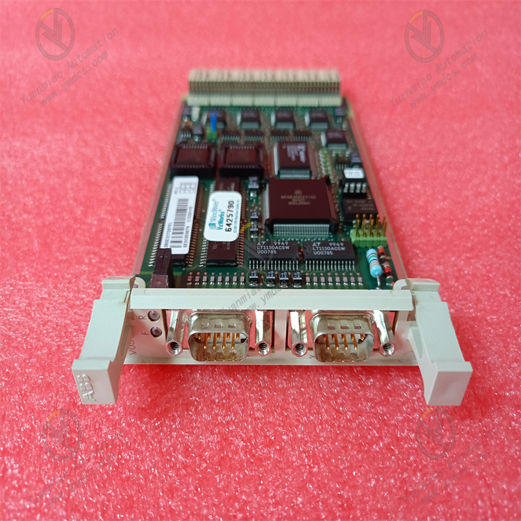
ABB CS513K02 3BSE004773R1 is a compact communication interface module belonging to the ABB MasterBus 300E communication interface module series. As a core communication component of open control systems, it serves as an upgraded and adapted version of the CS513K01 model. Its core positioning is to act as a hub for data transmission and interaction, enabling seamless connection between ABB ACS510/ACS550 series drives, Safeguard 400 series safety control systems and external devices such as PLCs, HMIs and upper computers. With its enhanced multi-protocol compatibility and higher transmission stability, it ensures efficient cross-device data transmission and accurate delivery of control commands. Widely used in automated production lines across multiple industries including process control, robot control, conveyor systems, HVAC systems, as well as printing, packaging, petrochemicals and power generation, it provides more reliable communication support for the coordinated operation of industrial systems.
I. Product Features
1. Enhanced Multi-protocol Compatibility and Superior Cross-device Interaction Capability
2. High-precision Data Processing for High-load Control Tasks
3. Broader System Compatibility and More Flexible Application Scenarios
4. Industrial-grade Reliable Design with Upgraded Maintenance Convenience
II. Technical Parameters
1. Basic Parameters
- Model: ABB CS513K02 3BSE004773R1
- Product Type: Compact communication interface module
- Product Series: MasterBus 300E communication interface module series
- Core Functions: Cross-device data transmission, control command interaction, remote diagnosis and maintenance, fault early warning
- Compatible Systems: ABB ACS510/ACS550 series drives, Safeguard 400 series safety control systems, Advant Controller 410 control systems
- Communication Protocols: Modbus RTU, ASCII, Profibus, MasterBus 300, MasterBus 300E, Modbus TCP/IP
- Interface Types: USB 2.0, RS-232, RS-485, Ethernet (RJ45)
- Configuration Methods: Menu configuration, dedicated software configuration (supporting parameter import/export)
- Installation Method: TS35 standard rail mounting
- Maintenance Methods: Online debugging, remote diagnosis and maintenance, modular hot swap replacement, fault trend analysis
2. Electrical Parameters
- Supply Voltage: 24V DC ±20%
- Power Consumption: Typical value 2.2W, maximum 2.8W
- Maximum Input Current: 5mA or 0.5A (depending on interface type)
- Analog Input Range: 0~10V DC voltage signal, 4~20mA current signal
- Analog Output Range: 0~10V DC voltage signal, 0~20mA current signal
- Sampling Rate: 100kHz
- Resolution: 16-bit
- Signal Acquisition Error: ≤±0.05% FS
- Communication Rate: RS-485 interface up to 115.2 kbps; Ethernet interface 10/100 Mbps (auto-negotiation)
- I/O Points: 32 points (16 digital inputs, 16 digital outputs, expandable to 48 points)
- Input Type: Single-ended and differential
- Output Type: Relay/Transistor (optional)
- Output Frequency: 200Hz
- Program Capacity: 500
- Data Capacity: 300
3. Environmental Parameters
- Operating Temperature: -25°C ~ +70°C
- Storage Temperature: -40°C ~ +85°C
- Relative Humidity: 5% ~ 95% RH (non-condensing)
- Protection Rating: IP20
- Vibration Resistance: Compliant with IEC 60068-2-6 standard (10~500Hz, acceleration 5g)
- Electromagnetic Compatibility: Compliant with EN 55011 and EN 55022 industrial electromagnetic interference protection standards, suitable for high-interference industrial field environments
- Certification Standards: CE certification, EMC enhanced certification
4. Physical Parameters
- Dimensions: 88mm×30mm×28mm (W×H×D)
- Net Weight: Approximately 0.12kg ~ 0.22kg
- Housing Material: Industrial-grade flame-retardant plastic (enhanced type)
- Terminal Type: Plug-in terminal with anti-misplug design, facilitating wiring and maintenance
- Status Indicators: Power light (PWR), Run light (RUN), Communication status light (COMM), Fault light (FAULT), Alarm light (ALM)
III. Working Principle
The core working logic of the ABB CS513K02 3BSE004773R1 communication interface module is "Power Supply - Protocol Adaptation - Data Interaction - Condition Monitoring - Fault Early Warning". On the basis of retaining the core workflow of the previous model, it optimizes the data processing and diagnosis mechanism, with the specific workflow as follows:
- Power Supply and Initialization: The module is connected to a standard 24V DC power supply. The internal enhanced power module performs voltage stabilization, filtering and overvoltage protection processing to provide stable power for core components such as the processor, communication interfaces and data storage units. At the same time, it automatically loads preset configuration parameters (communication protocol type, baud rate, address code, data format, etc.) and completes system initialization self-test, with newly added hardware-level interface status self-test. After passing the self-test, it enters the ready state, waiting to establish a communication connection with external devices.
- Protocol Adaptation and Connection Establishment: It automatically matches the corresponding communication protocol (such as Modbus RTU, Modbus TCP/IP, Profibus, etc.) according to the configuration parameters, and establishes a communication link with devices such as PLCs, upper computers and ACS510/ACS550 drives through the corresponding interface (RS-485, Ethernet, etc.). It supports automatic identification and adaptive calibration of device communication parameters, with the newly added protocol conflict detection function that can real-time monitor the protocol interaction status to avoid communication interruption caused by protocol conflicts.
- Data Collection and Interactive Transmission: It collects real-time data from control systems or field devices (such as drive operating parameters, sensor detection data, device status signals, etc.) through input interfaces. After rapid processing by the internal upgraded high-performance processor, the data is encapsulated according to the adapted communication protocol. The optimized data transmission mechanism supports batch data packet transmission to improve transmission efficiency. The encapsulated data is transmitted to the target device through the communication link, while receiving control commands or configuration parameters issued by the target device, which are parsed and then transmitted to the corresponding control system or actuator.
- Condition Monitoring and Fault Diagnosis: The system real-time monitors the power supply status, communication link connection status, data transmission integrity and internal component working status, and identifies abnormalities (such as communication interruption, data packet loss, parameter errors, power supply abnormalities, interface faults, etc.) through enhanced built-in diagnostic logic. When a fault is detected, the fault indicator is immediately turned on, alarm information is sent to the upper system through the communication link, and the fault code, fault occurrence time and data before and after the fault are recorded in the internal log. The newly added fault early warning function will turn on the alarm light and send an early warning signal when detecting parameter deviation from the normal range, facilitating maintenance personnel to take proactive intervention measures. It supports remote access to fault logs and early warning records for quick fault location and handling.
IV. Common Fault Troubleshooting
| Fault Phenomenon | Possible Causes | Troubleshooting and Solutions |
|---|---|---|
| Power light not on, module unresponsive | Abnormal supply voltage; reversed power polarity; poor contact of power supply lines; internal power module failure | Use a multimeter to measure the supply voltage to ensure it is 24V DC ±20%; check the positive and negative power connections to avoid polarity reversal; inspect the terminal connections of the power supply lines, re-plug and tighten them, and check for terminal oxidation or line damage; if the power supply and wiring are normal but the module is still unresponsive, judge that the internal power module is faulty and contact after-sales service for repair or replacement. |
| Ethernet communication interruption, unable to interact with upper computer | Incorrect IP address/subnet mask configuration; damaged/poor contact of Ethernet cables; faulty switch port; Modbus TCP protocol not enabled | Check that the IP address and subnet mask of the module and the upper computer are in the same network segment without address conflicts; inspect the Ethernet cables, replace damaged cables, re-plug the RJ45 connectors to ensure firm contact; test the corresponding switch port and replace it with a normal port; confirm that the Modbus TCP protocol is enabled through configuration software; if not, reconfigure and restart the module. |
| Data transmission errors or packet loss (RS-485 interface) | Signal interference; poor shielding of communication cables; transmission distance exceeding limits; excessive number of nodes; terminal resistor not configured | Replace the communication cable with a twisted-pair shielded cable, keep it away from strong interference sources such as frequency converters and motors, and ensure single-ended grounding of the shield layer (ground resistance ≤4Ω); check the transmission distance, add a signal repeater if it exceeds 1200 meters; confirm that the number of RS-485 nodes does not exceed 64; if exceeded, optimize the network topology; configure 120Ω terminal resistors at both ends of the RS-485 bus to improve signal stability. |
| Unable to establish communication with ACS550 drive | Unconfigured communication parameters of the drive; incompatible protocols between the module and the drive; faulty connection lines; communication interface failure of the drive | Enter the ACS550 drive parameter setting interface and configure communication parameters (address, baud rate, protocol type) matching the module; confirm that both the module and the drive adopt compatible protocols (such as Modbus RTU); inspect the connection lines between the module and the drive to repair open or short circuits; test the drive communication interface separately; if the drive interface is faulty, repair or replace the drive interface components. |
| Alarm light always on without fault alarm | Parameter deviation from normal range; sensor signal drift; unstable communication link; unreasonable alarm threshold setting | Check the alarm records through configuration software to locate the deviated parameters; calibrate the corresponding sensors to eliminate signal drift issues; inspect the communication link, optimize wiring or add anti-interference devices; reconfigure the alarm threshold according to actual on-site working conditions to avoid false alarms. |
| Frequent module restart or crash | Excessive fluctuation of power supply voltage; poor internal heat dissipation; conflicting parameter configurations; incompatible firmware version; excessive load | Install a regulated power supply or UPS to ensure stable supply voltage; check the module installation environment, avoid close contact with other heat-generating equipment to ensure smooth heat dissipation; restore the module default parameters through software and reconfigure to eliminate parameter conflicts; confirm that the module firmware version is compatible with the adapted system; if incompatible, upgrade the firmware; check the I/O load to ensure it does not exceed the rated load; if exceeded, optimize the load configuration. |