Description
MOTOROLA AP-4 01-W3394F-03G
1. Product Overview
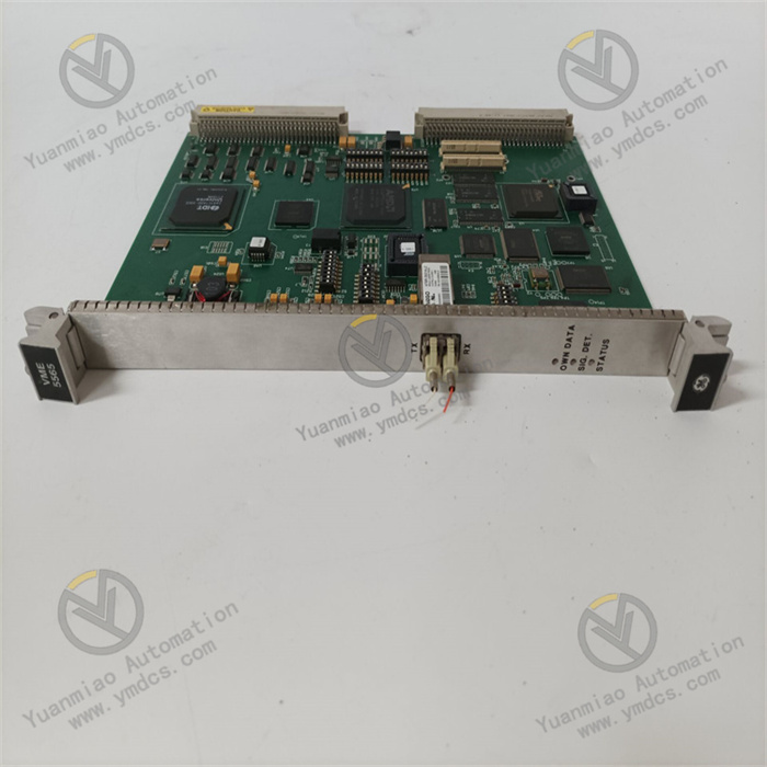
MOTOROLA AP‑4 01‑W3394F‑03G is a modular industrial control board / signal processing unit of the AP series, developed for harsh environments such as industrial automation, power control, and rail transit. It belongs to the supporting functional modules of Motorola’s classic MVME/VME bus architecture, and also meets the requirements of process signal acquisition and logic control for the AP‑series distributed control system. It serves as a key spare part for the upgrade of legacy industrial DCS/PLC systems and the retrofit of excitation / speed regulation control units.
2. Specifications
| Parameter Category | Details |
|---|---|
| Model | 01‑W3394F‑03G |
| Manufacturer | Motorola (USA; some produced in European factories) |
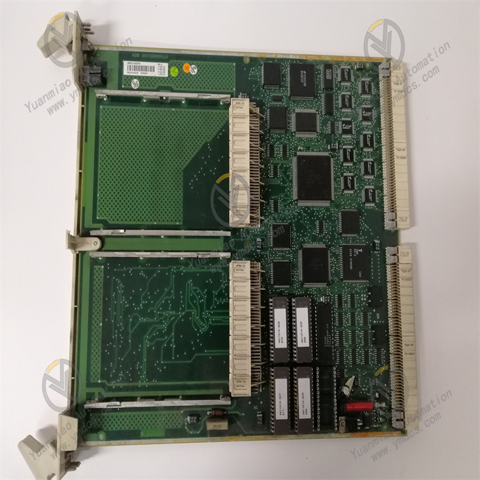
| Product Type | Industrial‑grade control module (VME bus process signal processing unit with logic control and I/O expansion functions) |
| Core Purpose | 1) Process control: analog / digital signal acquisition, calculation, and output for AP‑4 distributed systems;2) System upgrade: compatible with MVME series processor boards, replacing legacy I/O modules / control cards |
| Electrical Parameters | Operating power: 24 VDC standard industrial power supply (±10% fluctuation compatible); optional 110/220 VAC redundant power supply;Input: 8 channels 4–20 mA analog (compatible with 0–10 V), 16 channels digital DI;Output: 4 channels 4–20 mA analog, 8 channels relay / transistor DO;Power consumption: ≤ 12 W |
| Control Performance | Signal accuracy: ±0.075% FS; Response time: ≤ 5 ms;Supports PID closed‑loop control, logic interlock, parameter auto‑tuning;Multi‑channel synchronous sampling, max sampling rate 1 kHz |
| Dimensions | VME standard board: 233×160×20 mm;DIN rail mounting: 160×80×30 mm;Weight: approx. 0.8 kg;Fits VME chassis slots and 35 mm DIN rail without extra drilling |
| Communication Interface | Standard: RS485 (Modbus RTU), VME bus;Optional: Profibus DP, Modbus TCP, HART 7;Supports direct connection with Motorola dedicated configuration software and host SCADA |
| Protection Degree | Board IP20 (chassis mounting); fully sealed IP65 optional;Complies with IEC 60529; metal shielding housing; surge immunity complies with IEC 61000‑4‑5 |
| Environmental Rating | Operating temperature: -20 °C ~ +60 °C;Storage temperature: -40 °C ~ +85 °C;Relative humidity: 5% ~ 95% (non‑condensing);Vibration resistance: IEC 60068‑2‑6;Shock resistance: IEC 60068‑2‑27 |
| Other Features | Overvoltage / undervoltage / overcurrent / overheating / reverse polarity protection;Supports 2 parameter backup groups; online firmware upgrade;Metal housing shielding; CE and RoHS compliant; MTBF > 100,000 hours |
3. Functions & Features
(1) Dual‑Architecture Compatibility & Rapid Upgrade
- Process control: Direct replacement for legacy I/O modules of AP‑4 / MVME series, fully compatible with terminal definitions and communication address tables, no rewiring or recalibration required, with universal software drivers.
- System retrofit: Original functional board for AP‑4 systems, plug‑and‑play, automatic bus parameter identification, greatly reducing downtime in power plants and metallurgical plants.
Unified configuration software supports parameter backup / restore and batch download, lowering operation and maintenance complexity across multiple sites.
(2) High‑Precision Real‑Time Control & Signal Processing
- Adopts 16‑bit high‑precision ADC/DAC chips, analog acquisition accuracy ±0.075% FS, digital input response ≤ 1 ms, accurately capturing high‑frequency pulses and small signal changes.
- Built‑in temperature compensation algorithm maintains stable accuracy over the full temperature range of -20 °C ~ +60 °C; supports bidirectional flow measurement and nonlinear correction for differential pressure / level.
4–20 mA analog output ripple ≤ 50 μA, jitter‑free digital output, meeting the regulation requirements of precision actuators.
(3) Comprehensive Protection & High Reliability
- Hardware‑level protection: overcurrent, overvoltage, undervoltage, overheating, power reverse polarity, signal short‑circuit; output automatically blocked and reported to the system upon fault, with local LED alarm.
- Metal shielding housing + multi‑layer PCB grounding design, passes IEC 61000‑4‑3/4/5 tests for ESD, surge, and burst, operating stably in areas with dense inverters and high‑voltage cabinets.
Supports dual redundant power input with bumpless switching; redundant design for critical circuits, single‑point failure does not affect overall system operation.
(4) Flexible Communication & Convenient O&M
- Standard with Modbus RTU (RS485) and VME bus, optional Profibus DP, Modbus TCP, HART 7; range, damping, and alarm thresholds can be modified online via handheld communicator or host software.
- Built‑in multi‑color LED status indicators (power, communication, running, fault), internal event log storing up to 100 recent fault records for quick troubleshooting.
- Modular plug‑in design, replacement without removing the entire chassis / cabinet, can be completed by one person, with downtime controlled within 30 minutes.
4. Applications
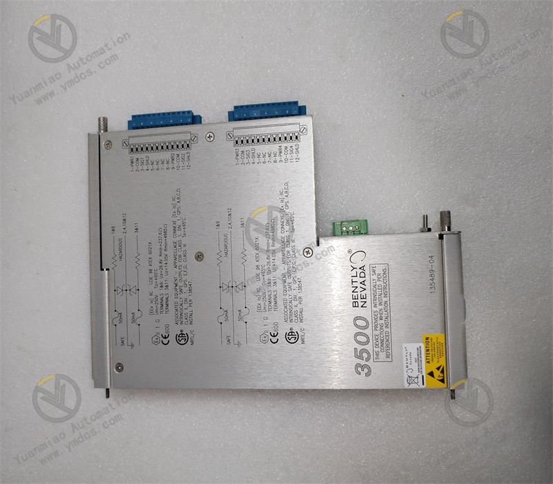
- Power industry: Process parameter acquisition and variable frequency control for auxiliary machines (fans, pumps) in thermal / hydropower plants; signal interlock for substation excitation systems (e.g., GFD233A); condition monitoring for power grid automation equipment.
- Petrochemical: Flow measurement for crude oil / product pipelines; closed‑loop control of reactor temperature, pressure, and level; I/O expansion in hazardous areas of offshore platforms.
- Metallurgy: Speed synchronous control for rolling production lines; temperature regulation for blast furnace hot blast stoves; current / voltage monitoring for rectifier cabinets in aluminum smelters.
- Rail transit: Auxiliary power control for locomotive traction systems; automation of station air conditioning, water supply and drainage; logic interlock for signaling systems.
- Legacy system retrofit: I/O module upgrade for Motorola MVME/AP series and third‑party DCS; centralized monitoring retrofit of factory control rooms; alternative solutions for obsolete systems without spare parts.
5. FAQs & Solutions
1. How to distinguish between the VME board version and DIN rail version?
2. How to troubleshoot signal drift / communication interruption during operation?
- Check that the 24 VDC / redundant power supply is stable, terminals are tight, and grounding meets single‑point grounding requirements (resistance < 4 Ω).
- Signal drift: Verify that the sensor cable shield is single‑end grounded; test I/O channels with a calibrator to distinguish module or sensor issues; check operating temperature and replace cooling fans if needed.
- Communication interruption: Check for bus address conflicts; ensure shielded twisted‑pair cable (≥0.5 mm²) is used; read communication error logs via software to identify protocol or hardware faults; verify by replacing with a spare module.
- Contact Motorola authorized service for module calibration or repair.
3. How to ensure stable operation in strong electromagnetic interference environments?
- Use IEC‑compliant shielded twisted‑pair cables; route analog and power cables separately (spacing ≥ 30 cm) and avoid parallel runs; install surge protectors on communication lines.
- Ensure reliable grounding of the metal housing (ground resistance < 4 Ω) and equipotential bonding in the cabinet.
- Regularly check firmware version and upgrade to the latest release via Motorola dedicated software to fix compatibility issues.
- Avoid mounting the module directly above or beside inverters, high‑voltage transformers, or contactors; keep distance ≥ 1 m from interference sources.