Description
MOTOROLA 01-W3839F-07A
1. Product Overview
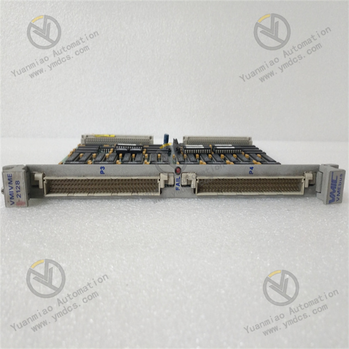
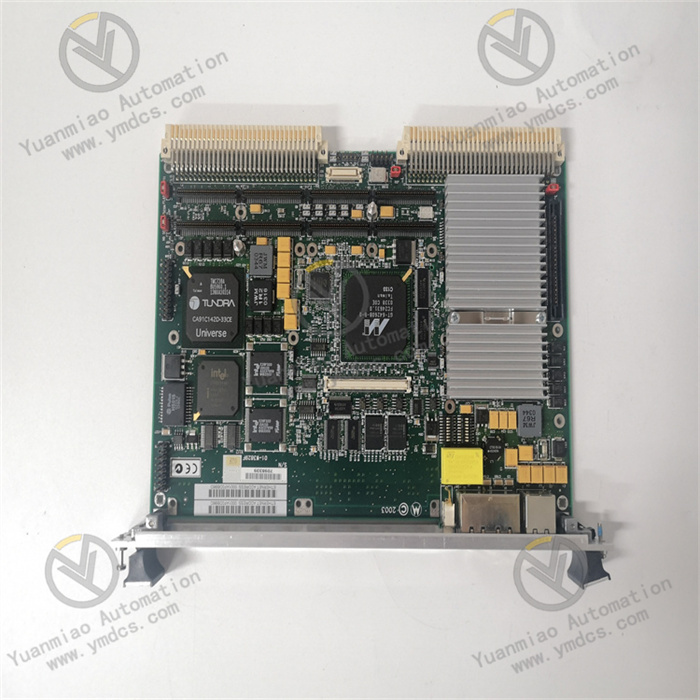
MOTOROLA MVME2434 01-W3839F-07A is a high-performance 6U VME bus Single Board Computer (SBC), designed for demanding applications requiring ultra-high real-time performance and reliability, such as industrial automation, power control, rail transit, and military embedded systems.
It serves as the core computing unit of distributed control systems based on the MVME/VME bus architecture, and is also a key original spare part for upgrading legacy CPU boards such as MVME2432/2433 and retrofitting excitation/speed regulation control stations.Based on the PowerPC architecture (MPC750 processor), the board adopts a standard 6U VME form factor, integrating high-performance computing, multi-protocol industrial communication, hardware-level redundancy protection, and strong anti-EMI design.
2. Specifications
| Parameter Category | Details |
|---|---|
| Model | MVME2434 01-W3839F-07A |
| Manufacturer | Motorola (USA, produced in European factories) |
| Product Type | Industrial-grade 6U VME bus Single Board Computer (SBC), integrating CPU, ECC memory, Flash, dual Ethernet, multi-serial ports, dual PMC expansion slots, VME64 bus bridge |
| Core Purpose | 1) System Master: real-time computing, VME bus arbitration, I/O data exchange, control strategy execution for MVME distributed systems;2) System Upgrade: direct replacement for legacy CPU boards such as MVME2432/2433, compatible with existing I/O modules and software drivers, no recompilation required |
| Electrical Parameters | Operating power: +5V DC, ±12V DC standard VME chassis power supply (±5% fluctuation compatible); optional dual redundant power input; Power consumption: ≤25W; with overvoltage/undervoltage/overcurrent/power reverse polarity protection |
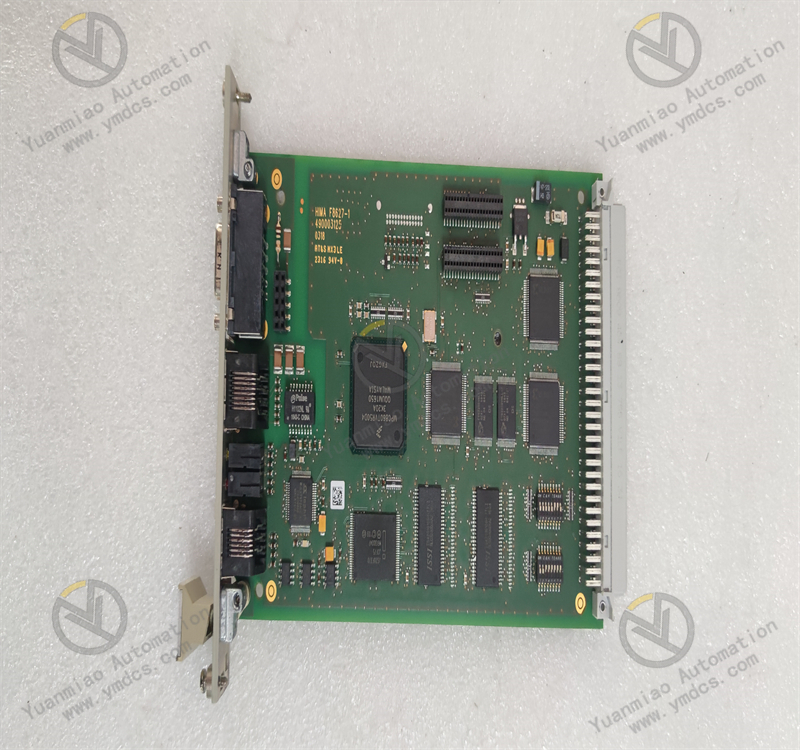
| Core Performance | CPU: MPC750 (PowerPC), 350MHz, with 1MB L2 cache;Memory: 64MB ECC SDRAM (upgradable to 512MB), 16MB on-board Flash for firmware and boot programs;OS support: VxWorks, LynxOS, pSOS+ and other mainstream real-time systems;Supports A32/D64 VME bus addressing |
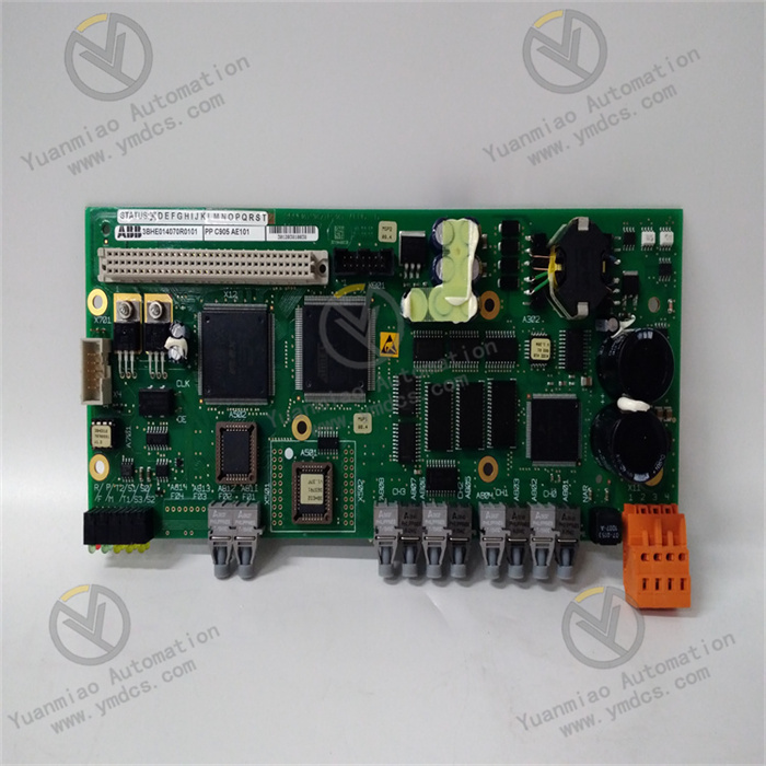
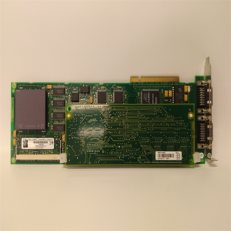
| I/O & Communication | Dual 10/100Mbps Ethernet ports; 4× RS232/422/485 serial ports (standard Modbus RTU, supports Modbus TCP); 2× PMC expansion slots (expandable for Profibus DP, HART 7, CANopen, etc.); VME64 bus interface (backward compatible with VME32) |
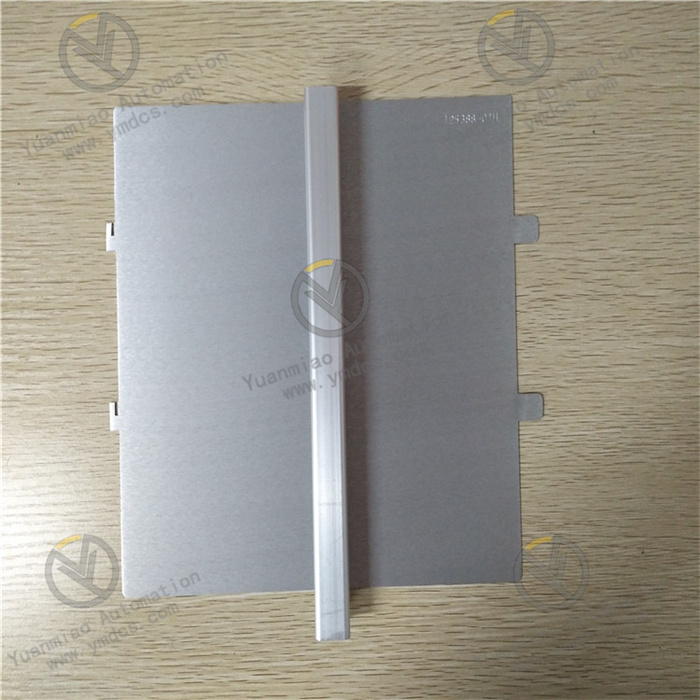
| Physical Dimensions | Standard 6U VME: 233×160×40 mm; fits standard 6U VME chassis slots; Weight approx. 0.9 kg; wire size 10–16AWG |
| Protection Degree | Board IP20 (chassis mounting), metal shielding enclosure; compliant with IEC 60529; surge immunity compliant with IEC 61000-4-5 |
| Environmental Rating | Operating temperature: -20°C ~ +60°C; Storage temperature: -40°C ~ +85°C; Relative humidity: 5%–95% (non-condensing); Vibration: IEC 60068-2-6; Shock: IEC 60068-2-27 |
| Other Features | Online firmware upgrade; dual parameter backup areas; hardware watchdog; multi-color LED status indicators; CE and RoHS compliant; MTBF > 100,000 hours |
3. Functions & Features
(1) Native VME Bus Compatibility & Rapid Upgrade
- Perfect System Compatibility: Direct replacement for legacy MVME2400 series CPU boards, fully compatible with terminal definitions, VME bus address tables and software drivers, no rewiring or recompilation needed, greatly reducing downtime in power plants and metallurgical plants.
- Plug-and-Play: As original main CPU board for MVME systems, automatically identifies bus parameters and I/O modules after power-on, without manual basic configuration.
- Unified Configuration Software: Supports Motorola dedicated configuration tools for firmware upgrade, memory settings, serial/Ethernet configuration, parameter backup/restore and batch download, reducing multi-site O&M complexity.
(2) High-Performance Real-Time Computing & Data Processing
- Adopts MPC750 processor + ECC SDRAM architecture, 350MHz with 1MB L2 cache, efficiently runs complex PID closed-loop control, logic interlock and synchronous control algorithms, meeting 1ms-level real-time response requirements.
- ECC memory automatically corrects single-bit errors and detects multi-bit errors, ensuring data accuracy under strong electromagnetic interference.
- On-board Flash supports permanent data retention after power loss, securing system firmware and boot parameters.
(3) Comprehensive Protection & High Reliability
- Full Hardware-level Protection: overcurrent, overvoltage, undervoltage, overheating, power reverse polarity, bus short-circuit; automatically blocks VME bus output, triggers local LED alarm and reports to host system on fault.
- Strong Anti-Interference Design: metal shielding enclosure + multi-layer PCB grounding + bus isolation transformer, passes IEC 61000-4-3/4/5 tests for ESD, surge and burst, operating stably in areas with dense inverters and high-voltage cabinets.
- Dual Redundant Power + Hardware Watchdog: supports bumpless switchover; hardware watchdog prevents program crash and auto-restarts on abnormality; single-point failure does not affect overall system operation.
(4) Flexible Communication & Convenient O&M
- Multi-Interface & Multi-Protocol: dual Ethernet, 4× serial ports (Modbus RTU) standard; supports Profibus DP, Modbus TCP, HART 7 (via PMC expansion cards); control parameters and alarm thresholds configurable online via handheld operator or host software.
- Status Visualization: multi-color LED indicators (Power, VME Bus, Ethernet, Run, Fault); built-in event log records up to 100 recent fault records with timestamps for quick troubleshooting.
- Modular Plug-in Design: standard 6U VME board, replaceable without full chassis disassembly, single-person operation, downtime controlled within 30 minutes.
4. Applications
- Power Industry: main control stations for auxiliary equipment (fans, pumps) in thermal/hydropower plants; synchronous control and logic operation for substation excitation systems; data processing and communication management for power grid automation equipment.
- Petrochemical: SCADA master stations for crude oil/product pipelines; complex closed-loop control of reactor temperature, pressure and level; VME bus control systems in hazardous areas of offshore platforms.
- Metallurgy: speed synchronous control master stations for rolling production lines; blast furnace hot blast stove temperature regulation; current/voltage monitoring and calculation for rectifier cabinets in aluminum smelters.
- Rail Transit: auxiliary control units for locomotive traction systems; main CPU boards for station integrated automation systems; logic interlock computing for signaling systems.
- Legacy System Retrofit: CPU board upgrade for Motorola MVME/AP series DCS; centralized monitoring retrofit of factory control rooms; replacement for obsolete VME systems without spare parts.
5. FAQs & Solutions
1. How to distinguish different versions of MVME2434 (e.g., 01-W3839F-07A vs 01-W3394F series)?
Check the PART NUMBER/VERSION label on the board:
- 01-W3839F-07A is a high-end model of MVME2434 (350MHz MPC750, larger cache/Flash, dual Ethernet).
- 01-W3394F mostly corresponds to MVME2432/2433 series (333MHz, basic configuration).
- Physically, MVME2434 is a standard 6U full-size board with VME gold fingers and dual PMC expansion slots.In software configuration, MVME2434 supports more advanced VME64 functions, while older models mostly provide basic VME32 functions.
2. How to troubleshoot program crash or communication interruption during operation?
- Check stability of VME chassis power (+5V/±12V), tightness of terminals, and compliance with single-point grounding (resistance < 4Ω).
- Program Crash: check whether the hardware watchdog is triggered (LED status); review ECC memory error logs; upgrade firmware via configuration software to resolve compatibility issues; replace chassis cooling fan if necessary.
- Communication Interruption: check for bus/IP address conflicts; ensure shielded twisted-pair cable (≥0.5mm²) is used; verify network connectivity with ping command; test with spare communication module or PMC card; contact Motorola authorized service for board calibration or repair.
3. How to ensure stable operation in strong EMI environments?
- Use IEC-compliant shielded twisted-pair cables; route analog and power cables separately (spacing ≥30cm), avoid parallel runs; install surge protectors on communication lines.
- Ensure reliable grounding of metal enclosure (ground resistance < 4Ω); equipotential bonding in the cabinet; separate grounding for VME chassis, not shared with other equipment.
- Regularly check board firmware version and upgrade to the latest release via Motorola dedicated software to fix potential compatibility issues.
- Avoid mounting the board directly above or beside inverters, high-voltage transformers or contactors; keep distance ≥1m from interference sources.