Description
ABB DO840 3BSE020838R1
I. Overview
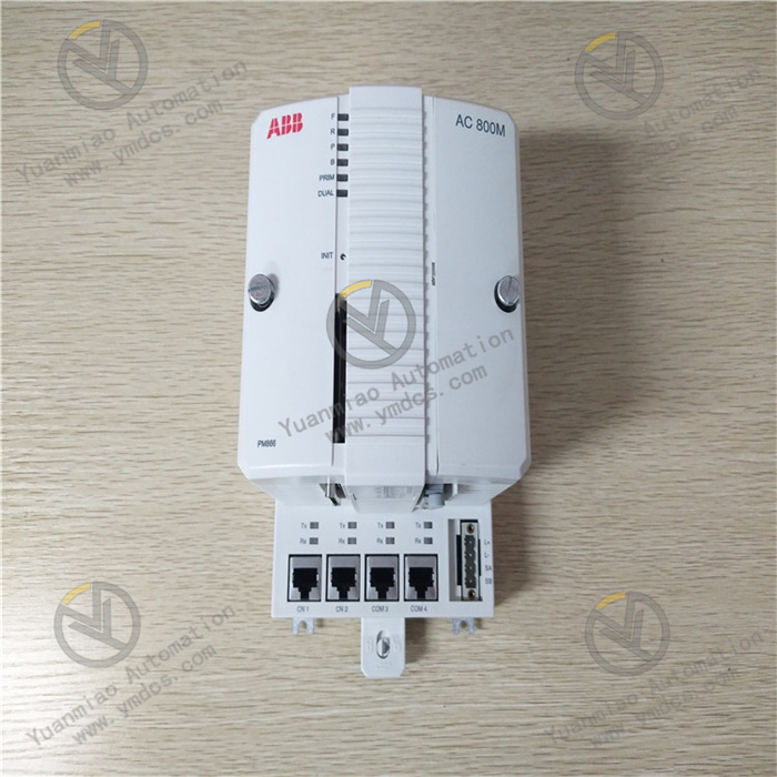
ABB DO840 3BSE020838R1 is a high-performance, high-density digital output module, positioned as a high-efficiency signal distribution and drive terminal between industrial automation control systems and multiple field execution devices. It is specially designed for the centralized signal output requirements of medium-to-large industrial scenarios. The module can accurately receive digital control commands issued by high-end ABB controllers such as the AC 800M. Through its internal high-performance signal processing and multi-channel drive circuits, it synchronously converts these commands into output signals that can directly drive external execution devices. This enables centralized start-stop control, status switching, and interlock action triggering for various digital execution devices including relays, contactors, solenoid valves, and indicator lights. It provides efficient, stable, and reliable signal output support for complex industrial process automation control in industries such as power, chemical, metallurgical, and large-scale manufacturing.
II. Product Features
High-Density Channel Configuration: Utilizes advanced high-density integrated design with 32 independent digital output channels. The compact and rational channel layout enables centralized drive control of multiple devices within standard cabinet installation space, significantly improving cabinet space utilization, reducing the number of modules deployed in medium-to-large systems, and lowering system construction costs and operation complexity.
Ultra-Stable Output Performance: The 32 output channels adopt a dual electrical isolation design with an isolation voltage of ≥1000V AC, which can completely block signal interference and crosstalk between channels, ensuring signal stability and accuracy during multi-channel synchronous output. It supports multiple output modes, is compatible with PNP/NPN drive types, and source/sink output can be flexibly configured via software, enabling precise adaptation to field execution devices with different load characteristics and delivering exceptional versatility.
High-End System Compatibility and Expansion Capability: Tailor-made for the ABB AC 800M series control system, it can seamlessly connect to the controller through dedicated communication interface modules such as the CI854. It adopts the PROFIBUS DP V2 high-speed communication protocol with a maximum data transmission rate of 12Mbps, ensuring synchronous issuance of multi-channel control commands and real-time status feedback. It supports cascade expansion of up to 32 same-series I/O modules, with a maximum expandable I/O point count of 1024, perfectly adapting to the expansion requirements of medium-to-large control systems.
Full-Link Intelligent Diagnosis Function: Built-in full-link self-diagnosis and real-time monitoring mechanism that continuously monitors module power supply status, accurate output voltage/current values of each channel, communication link integrity, connection status of external execution devices, and operating status of internal module circuits. When a fault is detected, it can locate the faulty channel and fault type (e.g., overload, short circuit, communication interruption, power supply abnormality, execution device jamming) in milliseconds. It intuitively indicates the fault area via local zone indicator lights and uploads standardized fault codes and detailed fault information to the controller and upper computer system through the communication bus, providing precise fault handling basis for operation and maintenance personnel and greatly shortening fault troubleshooting time.
Extreme Environmental Adaptability and Protection Performance: Incorporates military-grade core components and enhanced anti-interference circuit design, and has passed stringent Electromagnetic Compatibility (EMC) certification (compliant with standards such as EN 55011 and EN 55022). It features an operating temperature range of -40℃~+70℃, enabling stable operation in extreme temperature environments. It offers excellent vibration resistance (5g, 10Hz~200Hz) and shock resistance (25g, 11ms) performance, suitable for high-vibration industrial sites such as metallurgical and chemical plants. Each output channel is equipped with built-in overcurrent protection, short-circuit protection, reverse polarity protection, and surge protection circuits, which can effectively withstand on-site voltage fluctuations and line faults, protect the module and external execution devices from damage, and significantly enhance system operational safety and reliability.
- Intelligent Operation and Maintenance Design: Supports dual online hot-swapping at both module level and channel group level, allowing module installation, replacement, and single-channel group maintenance without interrupting overall system operation, thus greatly reducing substantial production losses caused by downtime of medium-to-large systems. It is equipped with high-definition local status indicator lights (Power, Run, Communication, Zone Fault, Channel Normal), enabling operation and maintenance personnel to quickly determine the overall module operating status and fault zone through the indicator lights. Combined with the upper computer system, it can accurately locate single-channel faults, significantly improving operation and maintenance efficiency.
III. Technical Parameters
1. Core Basic Parameters
- Product Model: ABB DO840 3BSE020838R1
- Product Type: High-performance, high-density digital output module
- Manufacturer: ABB Group
- Product Series: I/O Component of ABB AC 800M Series Control System
- Core Functions: Receive digital commands from controller, synchronous conversion and amplification of multi-channel signals, centralized drive of multiple field execution devices, real-time monitoring of channel status, full-link fault diagnosis and alarm, online hot-swapping
- Communication Method: Communicate with controller via PROFIBUS DP V2 bus (requires matching communication interface module such as CI854)
- Applicable System: ABB AC 800M Series Industrial Automation Control System
- Application Fields: Power industry (power plant auxiliary control system, substation integrated automation), chemical industry (large-scale process control execution unit, tank farm interlock control), metallurgical industry (smelting equipment auxiliary control, rolling production line drive), large-scale manufacturing industry (automotive complete vehicle production line, electronic component precision processing line), municipal engineering (large-scale sewage treatment plant, urban water supply pumping station), port logistics (large-scale loading and unloading equipment control), etc.
2. Electrical Performance Parameters
- Supply Voltage: 24V DC (voltage fluctuation range: 19.2V DC ~ 30V DC)
- Output Type: Digital output, compatible with PNP/NPN drive types, source/sink output selectable via software
- Channel Quantity: 32 independent digital output channels (dual isolation between channels, isolation voltage ≥1000V AC)
- Output Voltage Range: Rated output 24V DC (suitable for most industrial execution devices)
- Output Current: Maximum output current per channel ≤2A (subject to official manual); total output current of the module ≤32A (divided into 4 channel groups, maximum output current per group ≤8A)
- Output Response Time: Graded configurable via configuration software, minimum ≤0.5ms, maximum ≤100ms, supporting multi-channel synchronous output (synchronization error ≤10μs)
- Output Protection: Overcurrent protection (configurable threshold), short-circuit protection, reverse polarity protection, surge protection (±2kV)
- Fault Diagnosis Range: Channel short circuit, output overload, power supply voltage abnormality (overvoltage/undervoltage), communication link interruption, channel open circuit, execution device fault (jamming/burning), internal module circuit fault
- Communication Interface: Connect to communication interface module (e.g., CI854) via I/O bus
- Communication Protocol: Supports PROFIBUS DP V1/V2 protocol, compatible with DPV2 synchronization mode
- I/O Expansion Capability: Supports cascade expansion of up to 32 same-series I/O modules, maximum expandable I/O point count up to 1024
- Driven Device Type: Field relays, AC contactors, DC solenoid valves, industrial indicator lights, medium-sized drive pumps, fans, electromagnetic clutches, servo driver trigger terminals, and other digital execution devices
3. Environmental and Physical Parameters
- Operating Temperature: -40℃~+70℃
- Storage Temperature: -40℃~+85℃
- Relative Humidity: 5%~95% RH (no condensation, resistant to short-term condensation environment)
- Vibration Resistance: 5g, 10Hz~200Hz (sine wave), compliant with IEC 60068-2-6 standard
- Shock Resistance: 25g, 11ms (half-sine wave), compliant with IEC 60068-2-27 standard
- Protection Grade: IP20 (module itself); IP54 (when installed in standard industrial cabinet)
- Weight: Approximately 1.2kg (module itself); 3.0kg (including transportation package)
- Installation Method: Rack-mounted installation (adapted to ABB standard I/O cabinet, compliant with IEC 60917 standard)
- Dimensions (Length × Width × Height): 180mm × 105mm × 65mm (subject to official manual)
- Special Functions: Online hot-swapping (module level/channel group level), independent dual isolation of channels, full-link online diagnosis, multi-channel synchronous output, signal filtering, intelligent load detection
IV. Working Principle
The core working principle of ABB DO840 3BSE020838R1 is a closed-loop workflow of centralized command receiving - synchronous signal processing - multi-channel drive output - full-status feedback - intelligent fault diagnosis. Through the coordinated operation of the communication receiving unit, signal synchronization processing unit, multi-channel output drive unit, and full-link fault diagnosis unit inside the module, it realizes accurate conversion of controller commands and centralized and reliable drive of multiple field execution devices. The specific working process can be divided into five core stages:
Stage 1: System Initialization and Parameter Configuration StageAfter the module establishes a connection with the communication interface module (e.g., CI854) of the ABB AC 800M controller via the I/O bus and is connected to the 24V DC power supply, it automatically completes initialization and startup, performing a full internal circuit inspection, calibrating 32 output channels one by one, verifying communication link integrity, and conducting load matching detection. Operation and maintenance personnel complete the basic configuration of output response time, fault diagnosis threshold (e.g., overcurrent threshold), output type (PNP/NPN), channel grouping, synchronous output mode, and communication parameters through the ABB Control Builder M configuration software, ensuring the module is precisely adapted to the controller and various types of field execution devices, and meeting the centralized control and synchronous response requirements of medium-to-large systems.
Stage 2: Centralized Controller Command Receiving StageBased on the logic operation results of complex industrial processes, the AC 800M controller transmits multiple digital control commands (e.g., commands for coordinated start-stop of multiple devices, interlock action triggering) to the communication interface module at high speed via the PROFIBUS DP V2 bus. The communication interface module integrates and converts these multiple commands into a format recognizable by the I/O bus, and transmits them synchronously to the communication receiving unit of the DO840 module. The receiving unit performs parallel verification on the multiple commands, filtering invalid commands, interference signals, and format error commands to ensure the accuracy and integrity of command transmission.
Stage 3: Synchronous Signal Processing and Amplification StageThe verified multiple control commands are transmitted to the signal synchronization processing unit inside the module. According to the preset synchronization strategy, the processing unit converts these multiple commands into standardized synchronous drive signals. For execution devices with different grouping and load characteristics, the drive circuit of the corresponding channel group accurately amplifies the power of the standardized signals, ensuring that each output signal has sufficient driving capacity to stably drive various execution devices to act synchronously or asynchronously.
Stage 4: Multi-Channel Output Drive and Status Collection StageThe amplified multi-channel drive signals are synchronously transmitted to the corresponding field execution devices through 32 independent output channels, triggering the devices to complete preset actions (e.g., synchronous opening of multiple solenoid valves, coordinated pull-in of multiple relays). Meanwhile, the module real-time collects the output voltage and current signals of each output channel through the built-in high-precision current/voltage acquisition circuit, recording the channel operating status and load change conditions, providing real-time and accurate data support for subsequent full-status monitoring and fault diagnosis.
V. Common Fault Troubleshooting
1. No Signal Output/Output Abnormality in Partial/All Output Channels
2. Frequent Fault Alarms/False Alarms of Output Channels
3. Abnormal Communication Between Module and Controller
4. Module Fails to Start/Power Indicator Light Has No Response