Description
1. Product Overview
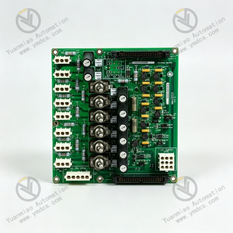
GE IS2020JPDBG01 is an original‑manufactured AC power‑distribution module dedicated for the Mark VI / VIe control system. It serves as a core power‑supply accessory board for turbine, gas‑turbine and generator‑set control systems, and is widely deployed in thermal‑power plants, gas‑turbine power stations and combined‑cycle power‑plant drive‑control systems.
Acting as the AC power‑distribution hub of the whole control system, this module integrates AC power filtering, voltage‑stabilized current distribution, circuit overload protection, multi‑channel power output and hardware diagnostic monitoring. It provides stable, compliant AC power supply to master control boards, I/O modules, signal loops and diagnostic units of the system.
The unit is equipped with two independent AC distribution circuits and built‑in fuse‑based overload‑protection structures, together with dedicated power‑filtering units to effectively suppress grid harmonics, voltage noise and transient surges, so as to guarantee clean and stable power supply for the control system.
The printed‑circuit board adopts an industrial‑grade reinforced coating, offering resistance against dust, humidity and electromagnetic interference. It is designed for long‑term 7×24‑hour non‑stop operation in control‑room environments of power stations. This module is a standard core component for new‑project deployment, replacement of aged power modules and stability upgrading of power‑supply systems in GE Mark VI / VIe control installations.
2. Technical Parameters
2.1 Basic Specifications
‑ Product Model: IS2020JPDBG01
‑ Product Series: GE IS2020 Power‑Module Series for Mark VI / VIe Control Systems
‑ Product Type: AC Power‑Distribution Board
‑ Core Function: Centralized AC power distribution, filter‑based voltage stabilization, circuit protection and power‑supply monitoring for gas‑turbine / steam‑turbine control systems
‑ Compatible Systems: GE Mark VI, Mark VIe turbine and generator‑set control systems
‑ Compatible Boards: Fully interoperable with JPDS, JPDF, JPDE, JPDM series boards and PPDA I/O assemblies
‑ Mounting Method: Standard cabinet slot‑mounting, compatible with the standardized layout of GE system cabinets
‑ Structural Feature: Full‑board anti‑corrosion reinforced coating, anti‑oxidation and anti‑corrosion properties; no mechanically wearable components for long‑term reliable operation
2.2 Electrical & Power‑Distribution Parameters
‑ Input Voltage: Dual‑range AC input at 115 V / 230 V, adapted to standard industrial power‑supply systems of power stations
‑ Input Circuits: Two independent AC input loops with partitioned, non‑interfering power distribution for improved power‑supply redundancy
‑ Rated Current per Loop: 20 A rated current‑carrying capacity to meet full‑load power‑supply requirements for all system boards
‑ Protection Configuration: Six fuse‑protected switch‑output channels and eight fuse positions, providing independent overload and short‑circuit protection for each branch circuit
‑ Filtering Performance: Dual‑line built‑in filters effectively suppress grid harmonics, voltage spikes and high‑frequency interference and deliver clean output power
‑ Supported Loads: Supplies stable power simultaneously to master‑control cards, communication boards, I/O acquisition cards and diagnostic modules
2.3 Interface & Diagnostic Parameters
‑ Terminal Block: Dedicated TB1 terminal strip for mains‑power input and branch‑circuit output wiring
‑ Connectors: 2 sets of 9‑position Mate‑n‑Lok connectors and 1 set of 5‑position Mate‑n‑Lok connectors complying with system‑standard wiring protocols
‑ Diagnostic Ports: Two 50‑pin ribbon‑cable diagnostic interfaces (P1 / P2) for full‑board operational‑status diagnosis and fault‑data retrieval
‑ Condition Monitoring: Real‑time monitoring of input voltage, loop current, fuse status, load anomalies and power‑supply faults
‑ Functional Characteristics: No on‑board parameter‑configuration capability; plug‑and‑play operation without program tuning, consistent with standardized system power‑distribution logic
2.4 Environmental & Protection Specifications
‑ Operating Temperature: ‑20 ℃ ~ +65 ℃ wide industrial temperature range, suitable for high‑temperature, constant‑temperature operation inside enclosed power‑station cabinets
‑ Storage Temperature: ‑40 ℃ ~ +75 ℃, satisfying requirements for long‑distance transportation and idle‑state storage
‑ Operating Humidity: 5 %‑95 % RH non‑condensing; resistant to humid, dusty and lightly‑oily environments in power stations
‑ EMC Immunity: Complies with power‑equipment electromagnetic‑compatibility standards and withstands strong EMI noise generated by gas turbines, variable‑frequency drives and high‑power equipment
‑ Insulation Protection: Insulation coating on the circuit board prevents electric leakage, short‑circuit faults and conductor oxidation, and reduces electrical‑failure risks
‑ Operational Reliability: Fully solid‑state board architecture with no moving mechanical parts; 7×24‑hour continuous operation without performance degradation or parameter drift
3. Product Functions and Core Advantages
3.1 Core Functions
Centralized multi‑channel AC power distribution
As the dedicated power‑distribution core for Mark VI / VIe systems, the module divides and stabilizes the incoming 115 / 230 V AC supply, and distributes power precisely to internal boards, I/O units, diagnostic modules and signal loops. It realizes unified, well‑organized power management across the whole control system and avoids unregulated power delivery and uneven load sharing.
Power‑supply filtering and conditioning
Two high‑performance on‑board line filters suppress grid‑borne harmonic interference, voltage spikes, transient surges and high‑frequency noise, correct voltage fluctuations and deliver clean, stable AC power. This eliminates board resets, data corruption and unintended logic actions triggered by power‑quality disturbances.
Overload and short‑circuit protection for branch circuits
Six independent fuse‑protected output channels with multi‑point fuse monitoring provide individual protection for each power‑supply branch. Upon overload, short‑circuit or over‑current events, the corresponding fuse trips and isolates the faulty circuit, preventing fault propagation that could cause total system power loss or permanent hardware damage.
Full‑board status diagnosis and fault tracing
Via the dedicated P1 / P2 diagnostic interfaces, the module continuously acquires input‑voltage, loop‑current, fuse‑status and load‑condition data. It accurately identifies faults such as phase loss, abnormal voltage, circuit overload, fuse blow‑out and loose connections, delivering actionable data for maintenance troubleshooting and root‑cause analysis.
Seamless system‑wide power‑supply interoperability
Natively compatible with the complete hardware architecture of GE Mark VI / VIe control systems, the board interfaces flawlessly with JPDS, JPDF, PPDA and other companion modules. Its power‑up sequencing and voltage parameters fully match factory specifications, ensuring stable power delivery throughout system startup, steady‑state operation and shutdown.
Long‑term continuous power‑supply assurance
Optimized for year‑round non‑stop power‑station operation, the module features adaptive‑load capability to cope with dynamic operating‑condition changes including system startup‑shutdown cycles and load variations. It provides uninterrupted stable power and mitigates risks of unit trip‑out or spurious interlock activation caused by power‑supply interruptions.
3.2 Core Advantages
‑ Original‑equipment full compatibility, zero‑risk integration
Purpose‑built for GE gas‑turbine and steam‑turbine Mark VI / VIe control systems. Pin‑out definitions, power‑supply ratings and distribution logic strictly follow factory standards. Direct drop‑in replacement of legacy units requires no modification to system programs, wiring schemes or power‑supply logic, delivering trouble‑free upgrades.
‑ Two‑tier protection architecture with superior power‑safety performance
The combination of upstream line‑conditioning filters and independent branch‑circuit fuses isolates single‑point faults while keeping unaffected sections of the system operational, substantially raising the overall safety level of the control‑system power supply.
‑ High‑efficiency power‑quality conditioning for enhanced system stability
Dual dedicated filter stages deeply attenuate industrial‑grid interference, eliminating intermittent board communication drop‑outs and erratic control behaviour induced by poor mains quality. Stable power at source strengthens the reliability of the whole automation system.
‑ Plug‑and‑play deployment for fast, low‑effort maintenance
No complex parameter programming or specialized tuning is required; the unit becomes operational once wired. Board‑level fault conditions are diagnosable, shortening troubleshooting cycles and reducing maintenance workload.
‑ Industrial‑grade durability and low lifecycle‑maintenance costs
The fully solid‑state circuit board with anti‑corrosion insulation coating offers excellent ageing, corrosion and interference resistance. No periodic calibration is necessary; routine visual inspections are sufficient for long‑term service, cutting power‑station maintenance expenditure.
‑ Power‑plant‑grade quality assurance for easy project acceptance
Manufactured to GE’s power‑generation equipment standards and validated under harsh operating conditions at large‑scale thermal‑power, gas‑turbine and combined‑cycle facilities. Fully compliant with acceptance specifications for control‑system equipment in new‑build and retrofit power‑station projects.
4. Typical Application Scenarios
‑ Gas‑Turbine Control Systems: Central AC power distribution, filtering and overload protection for Mark VI / VIe installations at large gas‑turbine power plants
‑ Steam‑Turbine Generator Control Systems: Centralized board power supply, voltage conditioning and circuit safety protection for steam‑turbine automation systems in thermal‑power and cogeneration plants
‑ Combined‑Cycle Power‑Plant Systems: Organized system‑wide power distribution and interference‑resilient power‑supply assurance for multi‑unit coordinated‑control installations
‑ Industrial Drive Automation Systems: Power‑supply‑board assemblies for generator‑set control systems at large industrial captive‑power stations and energy‑production sites
‑ Equipment Fault‑Protection Systems: Power‑supply monitoring and protection unit guarding against short‑circuit, overload and surge faults within the control system
‑ Legacy‑System Retrofit Projects: Replacement of ageing power‑distribution boards and stability‑upgrade modifications for existing GE Mark VI / VIe control installations
5. Installation, Commissioning and Maintenance Guidelines
Before installation, disconnect the main system power supply and cabinet power completely. Allow sufficient time for capacitor discharge, then remove dust, oil and debris inside the cabinet. Insert the module securely into its designated slot and fasten it firmly to prevent board loosening, poor‑contact connections and power‑supply anomalies caused by equipment vibration.
Strictly follow original‑equipment drawings to separate AC‑input loops, branch‑output loops and diagnostic‑interface circuits. Route high‑power and signal cables on segregated wiring layers to avoid electrical interference from power circuits and maintain clean power and stable signals.
Match the AC‑input voltage exactly to either the 115 V or 230 V operating range. Never apply out‑of‑specification voltages. Verify load ratings on each branch circuit to avoid overloading. Install fuses according to factory specifications; never over‑rate fuses or short‑circuit protection loops.
During initial commissioning, complete wiring continuity tests, output‑voltage verification and simulated‑load trials. Retrieve operational data via the P1 / P2 diagnostic ports to confirm correct performance of filtering, overload‑protection and fault‑alarm functions.
For routine maintenance, periodically inspect module operation‑indicator status, wiring‑terminal tightness and fuse integrity. Monitor supply voltage, circuit loads and fault logs via the host system, and identify hidden risks such as voltage drift, abnormal loading and cable ageing at an early stage.
Regularly clean dust and oil deposits from the module and cabinet interior. Maintain good cabinet ventilation and dry, dust‑free, corrosion‑resistant environmental conditions to prevent connector oxidation, insulation degradation, electric leakage and premature hardware ageing.
Faulty units shall be replaced exclusively with an original‑manufacturer GE IS2020JPDBG01 module. After replacement, restore the original wiring configuration and load settings, and perform power‑on tests, load‑verification checks and full‑system joint commissioning. Confirm that power‑supply stability, protection‑logic behaviour and diagnostic‑system performance remain identical to pre‑replacement conditions.