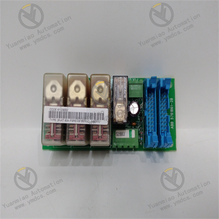
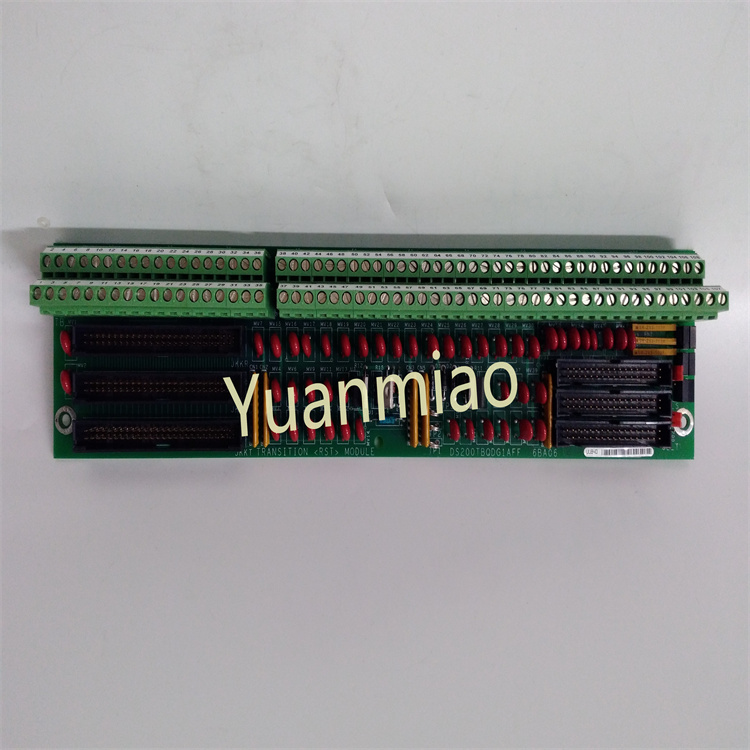
Description
1. Product Overview
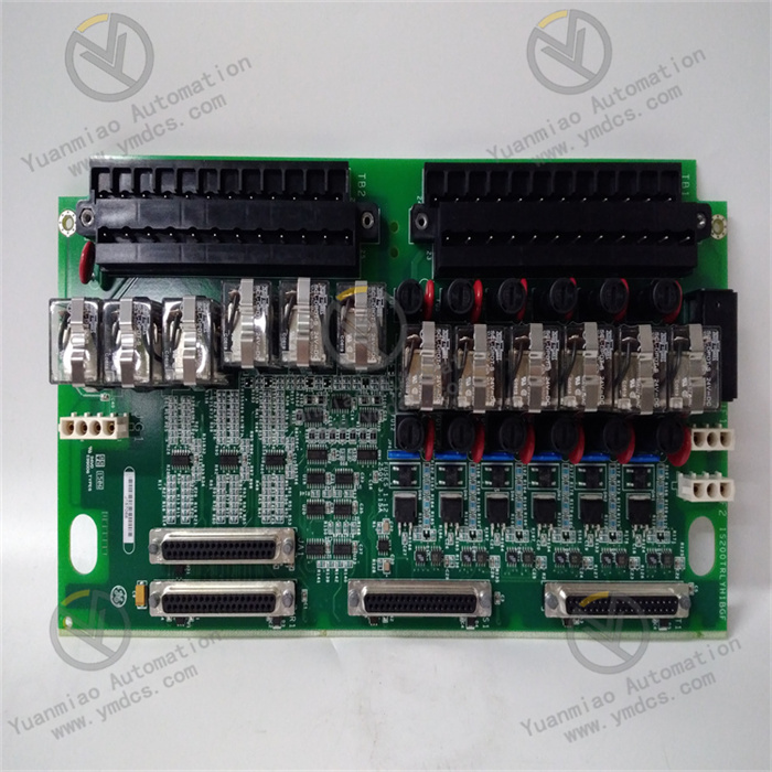
IS200TRLYH1BHH is a Turbine Relay Output Board (TRLY) of the IS200 series for GE Vernova (formerly GE) Speedtronic Mark VI turbine control system. It is a dedicated discrete‑output relay board for gas / steam turbine TCS (Turbine Control System).
Used with Mark VI VME control cabinets, it is widely deployed in control systems for gas turbines, steam turbines, generator sets and centrifugal compressors. Receiving control commands from the Mark VI main‑control CPU, the board drives on‑board relays to output passive dry‑contact signals. These signals are applied for solenoid‑valve actuation, alarm relays, interlock loops, trip‑signal output and local indicator lamp control. It serves as core hardware for discrete interlock and protection‑action output within the Mark VI turbine control system.
As a standard VME backplane‑plug‑in board, it has passed reliability tests including high‑temperature aging, vibration‑shock and EMC electromagnetic compatibility. It enables 7×24‑hour continuous stable operation in heavy‑EMI control cabinets of power plants and petrochemical facilities. It is frequently used for spare‑part replacement, on‑site maintenance and technical‑retrofit projects of gas‑steam turbine control systems.
2. Functional Features
2.1 Multi‑Channel Relay Dry‑Contact Output
Receives digital control commands from the main controller and drives multiple on‑board relays to output passive dry‑contact signals for circuit on‑off control. It supports actuation of field‑site equipment such as solenoid valves, audible‑visual alarms and interlock loops.
2.2 Relay Contact Galvanic Isolation
Galvanic isolation exists between relay coil side and contact side, separating the VME main‑control circuit from field primary actuator circuits. It suppresses back‑EMF and surge interference from field sites and protects the VME backplane and main‑control CPU module.
2.3 Relay Status Feedback Acquisition
The board acquires relay‑coil status and contact read‑back signals, feeding relay pull‑in / drop‑out status back to the main controller for real‑time output‑loop monitoring on upper‑level systems.
2.4 Hardware Self‑Test and Fault Diagnosis
On‑board self‑diagnosis circuits continuously monitor board power supply, relay‑coil faults, output‑loop anomalies and board hardware faults. Upon anomaly detection, fault alarms are triggered and pop‑up alerts appear on the upper‑level HMI.
2.5 High‑Speed VME Bus Communication
Bidirectional high‑speed communication with Mark VI main‑control CPU is implemented over the VME backplane bus. It receives relay‑actuation commands from the main controller and uploads relay status read‑back as well as board diagnostic information.
2.6 Standard VME Slot Mounting
Directly inserts into VME backplane slots inside Mark VI cabinets with locking‑latch structure for easy installation and removal. Uniform cabinet architecture for IS200‑series boards simplifies spare‑part replacement.
2.7 Harsh‑Industrial‑Environment Adaptability
Wide‑temperature operation, anti‑vibration, anti‑shock and high electromagnetic‑interference immunity. It adapts to power‑plant cabinet conditions including high temperature, dust and electromagnetic interference induced by high‑power frequency converters and motors.
3. Technical Specifications
3.1 Core Compatibility Parameters
| Item | Specification |
|---|---|
| Model | IS200TRLYH1BHH |
| Brand | GE Vernova (Formerly GE) |
| Product Series | IS200 Series, Mark VI Turbine Control System |
| Board Type | Turbine Relay Output Board (TRLY) |
| Compatible System | GE Speedtronic Mark VI TCS Turbine Control System |
| Mounting Method | VME backplane slot mounting |
| Core Interfaces | Relay dry‑contact output terminals, VME backplane bus interface, board status LED indicators |
| Core Functions | Relay contact output, loop status read‑back, galvanic isolation, hardware self‑diagnosis, VME‑bus data transmission |
| Typical Applications | Mark‑VI‑based control systems for gas turbines, steam turbines, generator sets and compressors; unit trip interlocks, solenoid‑valve control, alarm‑signal output |
3.2 Electrical Performance Parameters
| Item | Specification |
|---|---|
| Output Signal | Passive relay dry‑contact signal |
| Signal Processing | VME‑bus command parsing, relay‑coil driving, contact‑status read‑back, galvanic isolation |
| Bus Interface | VMEbus industrial bus |
| Power Supply | Power supplied via VME backplane |
| Diagnostic Functions | Relay‑coil fault detection, output‑loop diagnosis, on‑board power‑supply self‑test, LED status indication, fault upload to system |
| EMC Performance | Complies with power‑plant industrial EMC standards; immunity against interference from high‑power motors and frequency converters |
3.3 Environmental and Physical Parameters
| Item | Specification |
|---|---|
| Operating Temperature | Wide‑temperature range for industrial cabinet deployment |
| Storage Temperature | Wide‑temperature tolerance for spare‑part storage and transportation |
| Operating Humidity | 5 % ~ 95 % RH, non‑condensing |
| Environmental Resistance | Vibration‑resistant, shock‑resistant, electromagnetic shielding protection; suitable for power‑plant cabinet operating conditions |
| Mechanical Construction | Standard VME board, metal‑reinforced front panel, board locking latches |
4. Hardware Configuration & Structural Advantages
4.1 Core Hardware Configuration
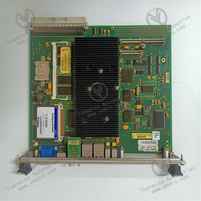
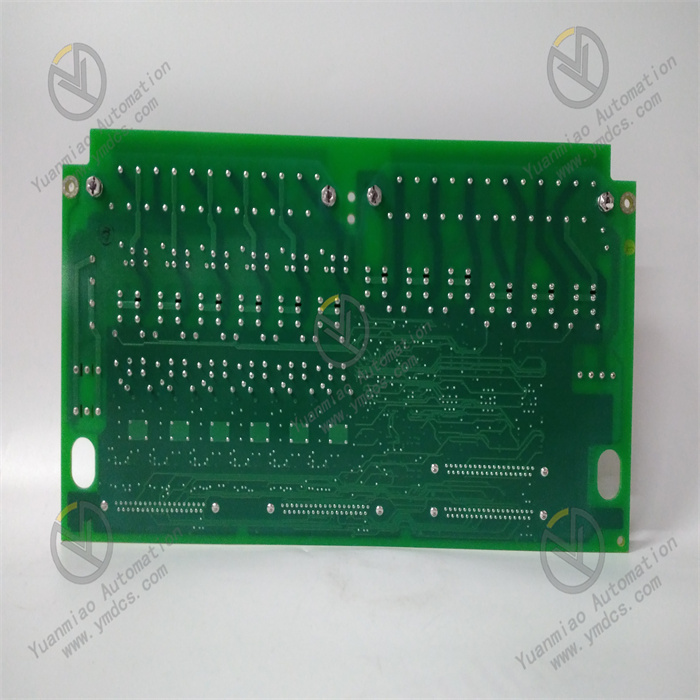
IS200TRLYH1BHH consists of VME‑bus interface circuit, command‑parsing unit, relay‑drive circuit, multiple sets of electromagnetic relays, contact‑status read‑back circuit, on‑board power‑conversion unit, self‑diagnosis monitoring circuit, front‑panel status LED indicators, VME gold‑finger interface and metal‑reinforced front panel.
The Mark VI main controller sends actuation commands over the VME bus. The on‑board command‑parsing unit receives signals, and the drive circuit energizes / de‑energizes corresponding relay coils to close or open dry contacts. The contact read‑back circuit captures real‑time relay status and feeds data to the main‑control CPU. Self‑diagnosis circuits continuously monitor board power supply, drive circuits and relay‑coil faults and activate front‑panel alarm LEDs upon faults. VME gold‑fingers realize backplane communication and power intake. The metal front panel enhances anti‑shock protection.
4.2 Structural & Engineering Advantages
The standard VME form factor supports plug‑in installation. Spare‑part replacement requires no extensive modification of external wiring and shortens maintenance downtime. Relays provide galvanic isolation between main‑control side and field loads, suppress back‑EMF generated by inductive loads, protect VME backplane and main‑control CPU, and reduce risks of hardware damage from surges.
Multiple relay channels are integrated onto one single board for high integration and reduced cabinet‑space occupation. Hardware‑level self‑diagnosis enables real‑time relay‑status monitoring and rapid faulty‑channel localization to shorten on‑site troubleshooting time. Fully compatible with the IS200 hardware ecosystem of Mark VI systems, it benefits from a mature spare‑part supply chain and is widely adopted for maintenance and upgrade‑retrofit projects of existing gas‑ and steam‑turbine power plants.
5. Working Principle
Working sequence of IS200TRLYH1BHH: Mark VI main‑control command → VME bus → on‑board command‑parsing unit → relay‑drive circuit → electromagnetic‑relay actuation & dry‑contact output; contact‑status read‑back → VME bus → Mark VI main‑control CPU; hardware self‑diagnosis runs in parallel.
During normal unit operation, the Mark VI main controller issues switching commands to this board according to control logic (interlock, alarm and trip logic). After receiving commands, the board drives corresponding relay coils. Relay dry contacts close or open to control field actuators including solenoid valves, alarm loops and trip loops. Meanwhile, the board continuously captures relay pull‑in / drop‑out status and feeds it back to the main controller for status supervision.
When unit protection logic is triggered, board relays act to output hard‑contact trip signals for emergency unit shutdown.
On‑board self‑diagnosis circuits uninterruptedly monitor power‑supply status, drive‑circuit conditions and relay‑coil faults. When faults are detected, front‑panel LEDs activate alarms and fault information is uploaded to DCS/HMI to notify maintenance staff, preventing protection mis‑operation or failure‑to‑trip caused by invalid relay outputs.
6. Common Faults and Troubleshooting
6.1 Fault LED illuminated after power‑on; system reports board fault
| Possible Cause | Troubleshooting Method | Remedial Action |
|---|---|---|
| Poor contact of VME backplane slot; oxidized gold‑fingers | Power off and extract the board; inspect VME gold‑fingers for oxidation and contamination | Clean gold‑fingers with lint‑free cloth; retry in an alternative VME slot |
| Abnormal backplane power supply; missing / under‑rated supply voltage | Measure supply voltage at VME slot terminals; inspect cabinet power modules | Troubleshoot cabinet power faults and restore backplane power supply |
| Damage to on‑board power‑conversion circuit | Backplane power is normal while faults persist across different slots | Replace with spare IS200TRLYH1BHH board |
6.2 Board communication interruption; CPU cannot send commands or read relay status
| Possible Cause | Troubleshooting Method | Remedial Action |
|---|---|---|
| VME backplane failure; damaged backplane pins | Inspect backplane pins for bending and corrosion; test communication of other boards in the same slot | Repair or replace VME backplane |
| Failure of board VME communication chip | Backplane confirmed normal via cross‑slot test; this board loses communication | Replace IS200TRLYH1BHH board |
| Lost board configuration parameters; configuration mismatch | Verify board hardware configuration inside Mark VI control software | Re‑download board hardware configuration parameters |
6.3 Main controller sends commands but field load does not respond
| Possible Cause | Troubleshooting Method | Remedial Action |
|---|---|---|
| Loose wiring of field load; oxidized terminals | Power off and inspect wiring terminals between external load and board relay terminals | Remove terminal oxidation and retighten connections |
| Aged and eroded relay contacts with poor contact performance | Power off; measure relay‑contact continuity with multimeter | Replace board or corresponding relay assembly |
| No freewheeling protection for field inductive loads; reverse high‑voltage damages contacts | Inspect field‑load loops; add freewheeling diodes / RC absorption circuits | Install surge‑absorption components and repair loops |
6.4 Persistent relay‑loop fault alarm reported by system with intact external wiring
| Possible Cause | Troubleshooting Method | Remedial Action |
|---|---|---|
| Damage to board relay‑drive circuit or coils | Switch commands to other healthy relay channels and compare fault status | Replace IS200TRLYH1BHH board |
| Incorrect board‑channel configuration parameters; wrong output‑type setup | Check channel parameters and output configuration inside Mark VI configuration software | Correct board‑configuration parameters, download configuration and restart controller |