Description
1. Product Overview
VT‑HNC100‑2‑30/P‑I‑00/G02 (Order No. R901134616) is a digital hydraulic axis controller of the Rexroth HNC100 series, a dedicated closed‑loop control unit for electro‑hydraulic servo systems. Developed for electro‑hydraulic servo drive systems, it is widely applied in high‑precision hydraulic positioning and force‑control scenarios such as metallurgical rolling mills, forging machine tools, injection‑molding equipment, material testing machines, construction machinery, and power‑station hydraulic actuators.
Receiving setpoint commands from the upper‑level PLC, the controller collects feedback signals from displacement and pressure sensors, outputs drive signals to control electro‑hydraulic servo valves, and realizes position closed‑loop, pressure closed‑loop and force closed‑loop control for hydraulic axes. Integrated with signal conditioning, PID control, status diagnosis and bus communication functions, it serves as the core control hardware of electro‑hydraulic servo systems.
It adopts standard DIN‑rail mounting. Having passed reliability tests including high‑low temperature, vibration‑shock and EMC electromagnetic compatibility, it supports 7×24‑hour continuous operation in industrial sites. It is frequently used for spare‑part replacement, equipment overhaul and technical‑retrofit projects of hydraulic servo systems.
2. Functional Features
2.1 Multi‑Mode Closed‑Loop Control
Supports position closed‑loop, pressure closed‑loop and force closed‑loop, as well as switch‑over control between position and pressure modes, suitable for processes including hydraulic‑servo‑axis positioning, pressure holding and force loading. Built‑in adaptive PID algorithm supports gain adjustment and feed‑forward compensation to improve dynamic response and suppress overshoot.
2.2 Multi‑Type Sensor Signal Acquisition
Accepts analog feedback signals from LVDTs, magnetostrictive displacement sensors, strain‑gauge pressure sensors and other devices. It filters, amplifies and conditions sensor signals to acquire high‑precision feedback values.
2.3 Servo‑Valve Drive Output
Provides standard ±10 V analog control signals to drive electro‑hydraulic servo / proportional valves. Output polarity, amplitude limiting and ramp rate are configurable to protect hydraulic valves and actuating cylinders.
2.4 Hardware Self‑Diagnosis and Fault Alarm
Continuously monitors supply‑voltage level, sensor wire breakage, signal over‑range, servo‑valve drive faults and internal hardware abnormalities. Faults trigger relay‑alarm output, and fault codes can be displayed on the upper‑level HMI.
2.5 Digital Communication and Analog Interfaces
Integrated analog input/output and digital DI/DO channels. It can receive setpoints from the host via bus and upload axis position, pressure and fault status. Parameters can be set locally via panel or configured by upper‑level software.
2.6 Standard DIN‑Rail Mounting
Industrial snap‑on mounting onto standard DIN rails for easy installation and removal. Compact modular design simplifies cabinet wiring and facilitates spare‑part replacement.
2.7 Harsh‑Industrial‑Environment Adaptability
Wide operating‑temperature range, vibration‑shock resistance and EMC protection. It adapts to high‑dust and heavy‑interference cabinet conditions in metallurgy and heavy‑duty machinery.
3. Technical Specifications
3.1 Core Compatibility Parameters
| Item | Specification |
|---|---|
| Model | VT‑HNC100‑2‑30/P‑I‑00/G02 |
| Order No. | R901134616 |
| Brand | Rexroth (Bosch Rexroth) |
| Product Series | VT‑HNC100 Digital Hydraulic Axis Controller |
| Product Type | Electro‑hydraulic servo closed‑loop controller |
| Compatible Objects | Electro‑hydraulic servo valves, proportional valves, hydraulic cylinder actuators |
| Mounting Method | DIN 35 mm standard rail mounting |
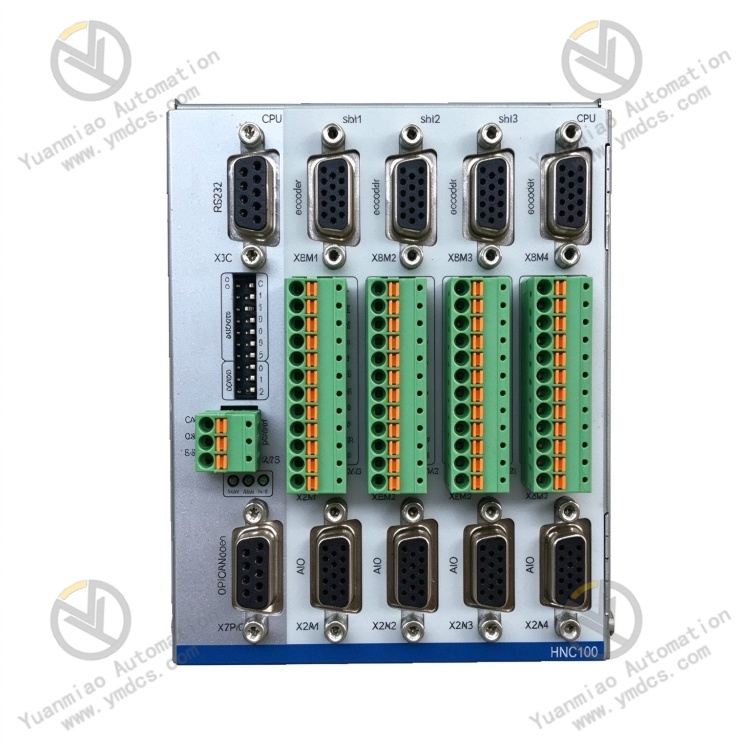
| Core Interfaces | Analog setpoint input, sensor feedback input, servo‑valve analog output, DI/DO digital terminals, communication interface, status LED indicators |
| Core Functions | Hydraulic‑axis position / pressure / force closed‑loop control, sensor‑signal acquisition, servo‑valve drive, parameter configuration, hardware fault self‑diagnosis |
| Typical Applications | High‑precision electro‑hydraulic servo control for metallurgical rolling mills, forging equipment, material‑testing machines, injection‑molding machines and power‑station hydraulic actuators |
3.2 Electrical Performance Parameters
| Item | Specification |
|---|---|
| Setpoint Signal | ±10 V analog command signal |
| Feedback Signal | Analog signals from LVDT, magnetostrictive displacement sensors and pressure sensors |
| Valve Drive Output | ±10 V, software‑configurable amplitude limit and polarity |
| Control Algorithm | Digital PID plus feed‑forward; multi‑loop switching for position / pressure / force |
| Power Supply | 24 V DC industrial power supply |
| Diagnostic Functions | Sensor wire‑break detection, signal over‑range alarm, power‑supply monitoring, drive‑fault detection, relay alarm output, LED status indication |
| EMC Performance | Complies with industrial EMC standards; tolerant of interference from high‑power hydraulic pumps and frequency converters |
3.3 Environmental and Physical Parameters
| Item | Specification |
|---|---|
| Operating Temperature | Wide‑temperature range for industrial cabinet deployment |
| Storage Temperature | Wide‑temperature tolerance for spare‑part storage and transportation |
| Operating Humidity | 5 % ~ 95 % RH, non‑condensing |
| Environmental Resistance | Vibration‑resistant, shock‑resistant, electromagnetic‑shielded; suitable for heavy‑industry cabinets |
| Mechanical Construction | Modular housing, DIN‑rail snap‑on fixture, terminal‑block connectors |
4. Hardware Configuration & Structural Advantages
4.1 Core Hardware Configuration
VT‑HNC100‑2‑30/P‑I‑00/G02 consists of analog‑signal‑conditioning unit, A/D conversion module, main‑control‑processing MCU, D/A servo‑valve drive output unit, DI/DO digital‑logic circuit, on‑board 24 V power‑conversion unit, self‑diagnosis monitoring circuit, status LED indicators, terminal‑block assembly and DIN‑rail snap‑on housing.
Position / pressure setpoint commands issued by the upper‑level PLC are sampled via the controller’s A/D converter. Feedback signals from displacement and pressure sensors are fed into terminals, conditioned and sent to the main‑control unit. The controller compares setpoints against actual feedback values and outputs analog drive signals to the servo valve via PID calculation to regulate cylinder motion. The self‑diagnosis unit continuously monitors sensor loops, power supply and drive channels and activates relay alarms upon faults. All field wiring connects via front‑end terminals, and the modular housing protects the internal circuit board.
4.2 Structural & Engineering Advantages
Snap‑on DIN‑rail mounting simplifies spare‑part replacement without extensive modification of on‑site hydraulic piping, shortening maintenance downtime. Built‑in signal‑conditioning circuits suppress interference from long‑sensor cables and guarantee feedback‑signal accuracy. A single controller integrates multiple closed‑loop functions, reducing the number of cabinet‑mounted modules and saving cabinet space. Digital PID supports on‑site online parameter tuning for convenient commissioning. Built‑in fault‑diagnosis functions rapidly localize faults in sensors and valve‑control loops to reduce troubleshooting time. The Rexroth HNC series offers good compatibility and is widely used for retrofits and spare‑part‑replacement projects of legacy hydraulic equipment.
5. Working Principle
Working sequence of VT‑HNC100‑2‑30/P‑I‑00/G02: Upper‑level setpoint command → analog / bus setpoint input → A/D sampling; Sensor feedback signal → terminal access → signal conditioning → A/D sampling; Main‑control unit compares setpoint versus actual feedback → PID + feed‑forward calculation → D/A conversion outputs servo‑valve drive signal → electro‑hydraulic servo valve regulates hydraulic‑oil flow → cylinder executes motion; Self‑diagnosis circuit runs in parallel to monitor hardware and sensor loops.
During operation, the host system transmits target‑position or target‑pressure commands. The controller samples cylinder‑displacement and cavity‑pressure feedback in real time, computes deviations, and outputs corresponding control voltages to drive the servo valve. It adjusts oil flow into the cylinder so that the cylinder quickly tracks setpoints to realize position closed‑loop or pressure‑holding control.
The controller continuously monitors power‑supply status, sensor wire breaks, signal over‑range and output‑drive faults. When an anomaly is detected, the front‑panel fault LED illuminates and the relay sends alarm signals to PLC/HMI to notify maintenance personnel and prevent equipment damage caused by hydraulic‑axis runaway.
6. Common Faults and Troubleshooting
6.1 Power‑on, fault LED stays on; system reports controller fault
| Possible Cause | Troubleshooting Method | Remedial Action |
|---|---|---|
| Abnormal 24 V DC supply; low voltage or power dropout | Measure voltage at controller power terminals; inspect power module and wiring | Rectify power‑supply circuit faults and restore stable 24 V DC supply |
| Loose or oxidized terminals | Power off, inspect all terminal connections and remove oxidation | Retighten terminals and clean oxidized surfaces |
| Damaged on‑board power‑conversion hardware | Power supply normal; fault persists after changing mounting position | Replace with spare VT‑HNC100‑2‑30/P‑I‑00/G02 controller |
6.2 Communication / command anomaly; upper‑level setpoints cannot be received
| Possible Cause | Troubleshooting Method | Remedial Action |
|---|---|---|
| Damaged shielding of analog setpoint cable; line interference | Check shielding‑grounding and cable integrity | Rewire and implement single‑end shielding grounding |
| Lost controller parameters; incorrect control‑mode configuration | Read controller parameters with Rexroth commissioning software | Restore factory defaults and re‑download axis‑control configuration |
| Damaged controller analog‑input channel | Perform comparative test by switching to alternative input channel | Replace VT‑HNC100‑2‑30/P‑I‑00/G02 controller |
6.3 Hydraulic‑axis oscillation, large positioning deviation, unstable cylinder motion
| Possible Cause | Troubleshooting Method | Remedial Action |
|---|---|---|
| Loose sensor‑feedback wiring; poor shielding‑grounding | Power off and inspect displacement / pressure‑sensor wiring and shielding | Retighten connections and apply proper shielding grounding |
| Improper PID gain and feed‑forward settings | Connect commissioning software and review dynamic curves | Retune PID parameters and optimize feed‑forward values |
| Damaged controller output‑drive channel | Disconnect servo valve and measure controller output signals | Replace VT‑HNC100‑2‑30/P‑I‑00/G02 controller |
6.4 Persistent sensor‑wire‑break alarm while sensor hardware is intact
| Possible Cause | Troubleshooting Method | Remedial Action |
|---|---|---|
| Open‑circuit sensor cable; poor terminal contact | Power off, measure continuity of sensor loop and inspect terminals | Repair signal cable and retighten terminals |
| Damaged controller sensor‑signal‑conditioning channel | Switch sensor to spare input channel for comparative test | Replace VT‑HNC100‑2‑30/P‑I‑00/G02 controller |
| Incorrect sensor‑type and‑range configuration | Verify sensor‑configuration parameters in Rexroth commissioning software | Correct sensor parameters, download configuration and restart controller |