Description
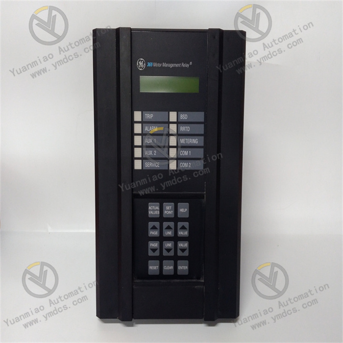
GE Multilin 369-LO-0-M-F-E-0-0
Overview
The GE Multilin 369-LO-0-M-F-E-0-0 is a specialized protective relay and control device designed for medium-voltage power systems. Engineered to ensure reliable operation in electrical distribution networks, this model integrates advanced protection, monitoring, and communication functions. It serves as a critical component for fault detection, circuit protection, and system control in industrial and utility applications, combining high-performance hardware with flexible software configurations.
Functional Features
- Comprehensive Protection Functions
- Supports multiple protection elements including overcurrent, under/overvoltage, distance protection, and directional overcurrent.
- Integrates automatic reclosing, breaker failure detection, and transformer differential protection for comprehensive system safeguarding.
- Configurable time-current characteristics enable precise coordination with upstream/downstream devices.
- Real-time Monitoring & Data Acquisition
- Measures and records electrical parameters (voltage, current, power, frequency) with high accuracy.
- Captures fault waveforms and event logs for post-fault analysis, supporting up to [X] event records.
- Provides real-time status indication via front-panel LEDs and LCD display.
- Flexible Communication Interfaces
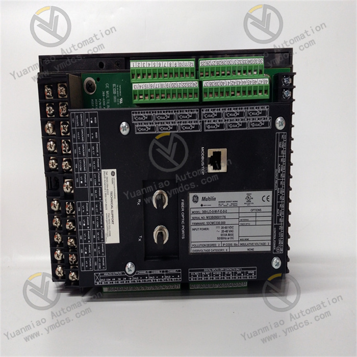
- Equipped with serial ports (RS-232/485) and Ethernet for seamless integration with SCADA systems.
- Supports industry-standard protocols (Modbus, IEC 61850, DNP3) for remote control and data exchange.
- Enables remote configuration and monitoring via web interface or dedicated software.
- User-friendly Configuration
- Intuitive setup through local HMI or PC-based configuration tools (e.g., GE Multilin ToolSet).
- Customizable protection schemes to adapt to diverse system requirements.
- Password-protected access levels for secure operation and maintenance.
Technical Parameters
| Category | Specifications |
|---|---|
| Rated Voltage | [e.g., 110-250V DC, 100-240V AC] |
| Current Inputs | [e.g., 5A or 1A CT secondary, 0.5% accuracy] |
| Voltage Inputs | [e.g., 120V or 220V VT secondary] |
| Communication | 2× RS-485, 1× Ethernet (10/100BaseT), supports IEC 61850-8-1/GOOSE |
| Protection Elements | Overcurrent (51), Earth fault (50N), Undervoltage (27), Overvoltage (59), etc. |
| Environmental | Operating temp: -25°C to +70°C; Storage temp: -40°C to +85°C; Humidity: 5%–95% RH |
| Certifications | Compliant with IEEE, IEC, and NEMA standards; CE, UL listed |
Working Principle
- Protection Logic Operation
The relay continuously monitors electrical parameters via current and voltage inputs. When detected values exceed preset thresholds (e.g., overcurrent or undervoltage), the protection algorithm triggers an output relay to trip the circuit breaker. The device prioritizes fault isolation while minimizing impact on non-faulted sections of the network. - Data Processing & Communication
Collected analog and digital data are processed by a microprocessor, which converts raw signals into actionable information. The communication subsystem packages data into protocol-compliant frames for transmission to supervisory systems, enabling remote monitoring and control. - Event Recording & Fault Analysis
Upon detecting a fault, the relay captures waveform samples and timestamps, storing them in non-volatile memory. This data supports post-fault analysis to identify fault causes and improve system reliability.
Operation Guide
- Installation Preparations
- Verify voltage/current ratings match system requirements.
- Prepare tools (screwdriver, multimeter) and ESD protection equipment.
- Mounting & Wiring
- Install the relay in a 19-inch rack or panel using provided brackets.
- Connect CT/VT inputs, control power, trip/close circuits, and communication cables per wiring diagrams.
- Ensure proper grounding to minimize electromagnetic interference.
- Configuration Steps
- Access the local menu via front-panel buttons to set basic parameters (CT/VT ratios, protection enable/disable).
- Use PC software to configure advanced settings (protection curves, communication protocols, event logging).
- Test functionality with simulated faults to validate protection responses.
- Troubleshooting
- No Power: Check fuse status, power supply connections, and voltage inputs.
- False Tripping: Review protection settings for incorrect thresholds or time delays.
- Communication Failure: Verify cable connections, protocol settings, and network connectivity.