Description
ABB CI534V04 3BSE010702R1
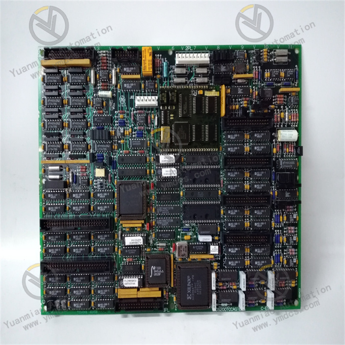
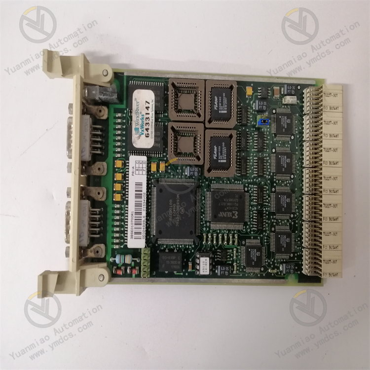
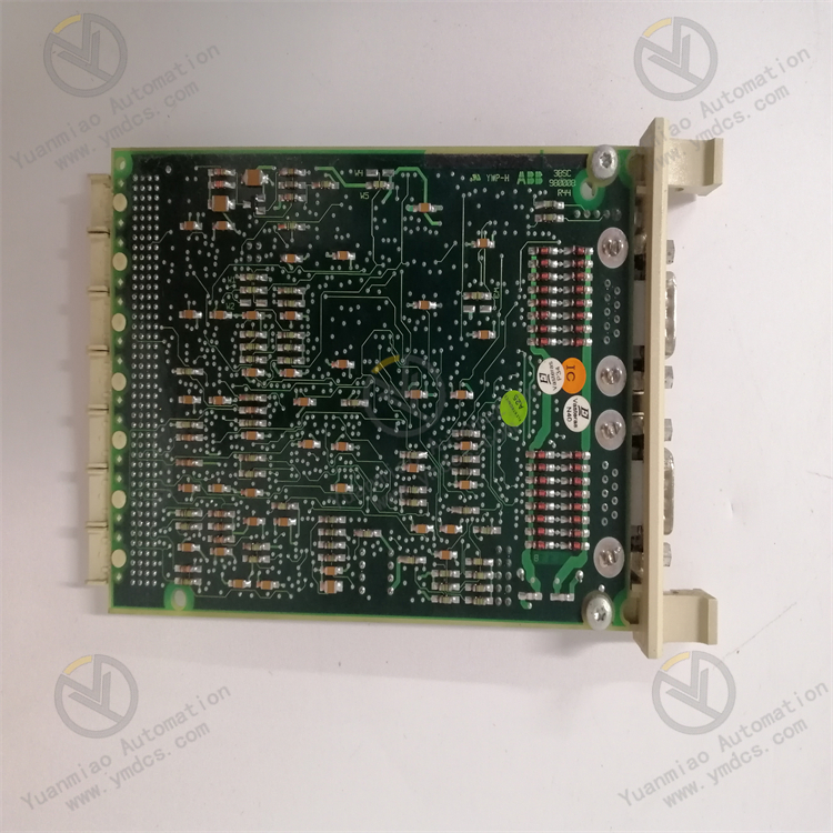
ABB CI534V04 3BSE010702R1 is an interface sub-module used in industrial automation systems.
Features and Applications
Powerful Communication Function: Utilizes advanced communication protocols, supporting the MODBUS RTU protocol to ensure seamless data transmission with other devices. It enables real-time monitoring and control of industrial processes.
Strong Adaptability: Operates within a wide power voltage range of 12–36VDC and a temperature range of -20°C to +70°C. With certifications such as CE and UL, it adapts to various industrial environments and meets the needs of different industrial scenarios.
Compact Design: Small in size and light in weight, it is easy to integrate into existing systems without affecting their functionality or performance.
Technical Parameters
- Interface Type: Allen-Bradley interface
- Communication Protocol: Modbus RTU
- Input Channels: 4
- Output Channels: 2
- Power Voltage: 12–36V DC
- Operating Temperature: -20°C to +70°C
- Dimensions: Length 90mm × Width 90mm × Height 30mm
- Weight: 0.1kg
Working Principles
Communication Principle: As an ABB interface module, it communicates with other devices using the MODBUS RTU protocol. During communication, it encapsulates instructions from the main controller or other devices into the format specified by the MODBUS RTU protocol and sends them via a serial port to connected slave devices. Meanwhile, it listens for signals on the bus, receives data returned by slave devices, parses and processes this data, and provides valid information to the main controller or other required devices.
Data Processing Principle: Received data undergoes verification first to ensure integrity and accuracy. If the data is error-free, it is processed according to its type and function code. For example, if the task is to read register data, the module retrieves the corresponding value from internal registers and returns it to the requester in the protocol format; if it is a register write instruction, the module writes the received data into the specified register. Digital signals are directly subject to logical judgment and processing, while analog signals are converted into digital signals via analog-to-digital conversion circuits before processing.
Signal Processing Principle: The module's input interfaces can receive signals from sensors or other devices, such as digital input signals (for binary information) and analog input signals (for continuous signals like temperature or pressure). These input signals are sampled, quantized, and encoded to convert them into digital signals that can be transmitted and processed on the internal bus. For output, the module generates corresponding signals based on internal control logic and processing results: digital output signals control the on/off status of external devices, while analog output signals adjust continuous variables of external devices (e.g., motor speed or valve opening).
Operation Guide
Installation: Before installation, verify that the device specifications match actual requirements and carefully read the installation manual. Install the module correctly in the control cabinet or designated location according to the manual, ensuring a secure fit. When connecting power and communication cables, pay attention to correct and secure wiring to avoid looseness or short circuits.
Parameter Setting: Configure parameters through programming software or related configuration tools, primarily including communication parameters such as baud rate, slave address, and parity check. Settings must align with the actual communication network configuration to ensure consistent parameters with other devices and enable normal communication.
Operation and Monitoring: After installation and setup, power on the module and wait for self-check completion to enter normal operation. During runtime, use programming software or a monitoring system to view the module’s working status, communication status, and data transmission in real time. If anomalies are detected, promptly troubleshoot and resolve issues.
Common Faults and Solutions
Communication Faults
- Unable to Communicate with Other Devices: May be due to poor communication cable connections, incorrect communication parameter settings, or a damaged communication interface. Solutions: Check cable connections for firmness and damage; verify that communication parameters match those of other devices; try replacing the communication interface or using a backup port.
- Erroneous or Lost Communication Data: May be caused by electromagnetic interference, excessively high communication rates, or outdated module firmware. Solutions: Use shielded cables with proper grounding, reduce the communication rate, and upgrade the module firmware to the latest version.
Power Supply Faults
- No Power to Module: Check if the power cable is properly connected, the power adapter is functional, and the input voltage is within the module’s specified range (12–36VDC). Solutions: Re-plug the power cable, replace the power adapter, or adjust the input voltage.
- Abnormal Power Indicator: Flashing or unusual colored indicators may signal unstable power voltage or internal overload/short circuits. Solutions: Improve power quality with a voltage stabilizer; disconnect external loads to gradually troubleshoot for short circuits caused by connected devices.
Input/Output Signal Faults
- Abnormal Input Signals: Check if the input signal source is working properly and if signals are within the module’s range. For analog inputs, also verify sensor connections and interference. Solutions: Adjust the signal source or replace the sensor if signals exceed the range.
- Abnormal Output Signals: Check if the output load is normal and free of short circuits or overloads. For analog outputs, verify configuration parameters and cable connections; for digital outputs, check if controlled devices respond properly and if the module’s output status matches expectations. Solutions: Repair or replace relevant components as needed.