Description
1. Product Overview
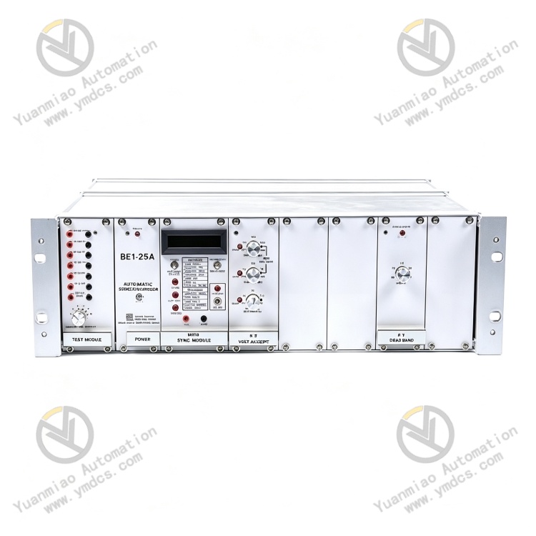
Basler BE1‑25A‑A2‑F5‑V3‑D0 is a microprocessor‑based high‑precision automatic synchronizing relay originally designed and manufactured by Basler Electric, USA. As the core synchronism‑check and grid‑connection control unit of the BE1‑25 series for generators, it is widely deployed for automatic precise synchronizing and grid‑connection of generator sets, diesel‑generator units, gas‑generator units and small‑scale hydro‑generator units.
Developed on a high‑performance micro‑processor architecture, the relay monitors in real‑time three critical grid‑connection parameters: voltage magnitude, frequency and phase‑difference between the generator side and the utility‑system side. It automatically completes speed matching, voltage matching and phase alignment, accurately captures the optimum closing instant, and commands the circuit‑breaker to close smoothly for paralleling. It thoroughly prevents unit shock, power‑grid oscillation and equipment damage caused by out‑of‑synchronization closing.
This specific model features dedicated configurations: A2 voltage adaptation, F5 frequency‑regulation output, V3 voltage‑rating specification and D0 interface configuration, which are optimized for grid‑connection conditions of medium‑and‑low‑voltage conventional generator sets. Built with industrial‑grade reinforced construction, it delivers strong anti‑interference performance, high stability and high measurement accuracy. Equipped with comprehensive self‑diagnosis and operating‑condition monitoring functions, it supports long‑term 7×24‑hour continuous stable operation. It serves as a standard core component for new synchronizing‑system deployment, legacy synchronizer replacement and grid‑connection‑system upgrading in power plants, captive industrial power stations and new‑energy supporting power stations.
2. Technical Parameters
2.1 Basic Specifications & Model Definition
‑ Product Model: BE1‑25A‑A2‑F5‑V3‑D0
‑ Product Series: Basler BE1‑25 Automatic Synchronizing Relay Series
‑ Product Type: Microprocessor‑based automatic precise‑synchronization control relay for generators
‑ Primary Application: Automatic precise synchronizing & paralleling, synchronism check, breaker‑closing logic control, auxiliary frequency‑and‑voltage regulation for generator units
‑ Configuration Definition:
A2 – Voltage threshold adaptation, enabling precise judgement of high‑low voltage deviation
F5 – Proportional pulse output for generator speed / frequency regulation
V3 – Standard voltage‑level configuration
D0 – Standard interface without additional customization
‑ Compatible Equipment: Diesel generators, gas generators, small hydro‑generator units, grid‑connection systems for industrial captive power plants
‑ Mounting Method: Standard cabinet flush‑mounting, suitable for standardized layout of power‑station control cabinets
‑ Net Weight: ≤6.2 kg, compact form factor to save cabinet installation space
2.2 Core Paralleling‑Detection Parameters
‑ Voltage‑difference Detection: Continuously adjustable threshold from 0.5 % to 5 %, strictly matching voltage‑magnitude deviation between power‑system and generator terminals to ensure voltage consistency before closing
‑ Phase‑angle Detection: Adjustable phase‑difference setting ranging from 1° to 99°, accurately locking the optimum closing phase to eliminate impact caused by phase offset during synchronization
‑ Slip‑frequency Monitoring: High‑precision slip‑frequency measurement adapting to low‑slip and high‑slip operating conditions, enabling accurate pre‑judgement of the breaker‑closing moment
‑ Closing Accuracy: Microsecond‑level timing judgement, fast paralleling response and minimal closing error, greatly reducing transient inrush current upon grid connection
‑ Frequency‑regulation Output Characteristic (F5): Dedicated proportional pulse output delivering continuously adjustable speed‑control signals to automatically match generator speed and achieve precise frequency tracking
2.3 Electrical & Operating Parameters
‑ Control‑supply Voltage: Compatible with standard industrial control power supply, tolerant of routine voltage fluctuations and transient disturbances in power‑station networks
‑ Operating‑frequency Range: 10 Hz ~ 500 Hz wide detection range, suitable for mains‑frequency and variable‑frequency generator operating conditions
‑ Output Contacts: Passive relay outputs with high contact‑rating and reliable actuation, capable of directly driving breaker‑closing circuits and governor‑control loops
‑ Sampling Performance: High‑precision voltage‑and‑frequency sampling chips with excellent linearity and zero drift, ensuring stable measurement accuracy during long‑term operation
‑ Logic Response: High‑speed built‑in paralleling‑calculation logic, dynamically tracking real‑time parameter variations and adapting to generator start‑stop cycles and load fluctuations
2.4 Environmental & Protection Specifications
‑ Operating Temperature: ‑20 ℃ ~ +60 ℃, wide industrial temperature range suited for high‑temperature enclosed‑cabinet environments inside power‑station control‑rooms
‑ Storage Temperature: ‑40 ℃ ~ +70 ℃, meeting requirements for long‑distance transportation and prolonged idle storage
‑ Operating Humidity: 5 %‑95 % RH non‑condensing, resistant to humid and dusty industrial power‑station environments
‑ Vibration & Shock Resistance: Industrially reinforced mechanical structure tolerating long‑term cabinet vibration and mechanical shocks from running machinery, free from hardware loosening or parameter shift
‑ Electromagnetic Compatibility: Complies with power‑industry EMC standards, providing immunity against strong electromagnetic interference generated by variable‑frequency drives and high‑power equipment, preventing false judgements and unintended operations
‑ Protection Design: Dust‑proof, moisture‑proof and EMI‑resistant construction optimized for long‑term continuous operation in industrial power‑station sites
3. Product Functions and Core Advantages
3.1 Core Product Functions
Fully‑automatic high‑precision precise‑synchronization paralleling
The relay acquires real‑time voltage, frequency and phase data from both generator and grid sides, automatically calculates synchronization deviations, and implements precise frequency‑and‑voltage matching logic to capture the optimal closing sequence. It achieves smooth, shock‑free grid‑connection and effectively safeguards the safety of generator stator, rotor and grid‑connected equipment.
Intelligent speed / frequency regulation control
Leveraging the F5 dedicated proportional‑pulse‑output function, the unit delivers continuously adjustable governor pulses according to the frequency difference between grid and generator, automatically regulating generator speed to rapidly reduce slip frequency, shorten synchronization waiting time and improve paralleling efficiency.
Programmable multi‑parameter threshold configuration
Key parameters including voltage‑difference limit, phase‑angle limit, slip‑frequency setting and closing advance time can be user‑defined, enabling flexible adaptation to different generator capacities and paralleling conditions to satisfy diversified synchronization requirements.
Bus‑condition monitoring and closing interlock
Integrated loss‑of‑bus‑voltage, abnormal‑voltage and frequency‑disturbance monitoring functions automatically block the closing circuit when generator‑terminal or grid‑side parameters fall out of permissible ranges. It prohibits unauthorized paralleling and prevents grid accidents and equipment damage caused by faulty synchronization.
Full‑scope fault self‑diagnosis and alarm
Built‑in diagnostics detect circuit anomalies, sampling failures, parameter out‑of‑tolerance, communication errors and unsuccessful breaker‑closing events. Front‑panel indicator lamps clearly display operating status and fault types to facilitate rapid troubleshooting by maintenance personnel.
Stable long‑duration continuous‑operation supervision
Optimized for 7×24‑hour unattended power‑station operation with stable computation logic, drift‑free sampling and zero false‑operation risk. It supports frequent repeated paralleling cycles and delivers high long‑term operational reliability.
3.2 Core Product Advantages
High‑precision synchronization control with minimized impact damage
Microprocessor‑based high‑accuracy calculation combined with multi‑dimensional closed‑loop parameter‑verification delivers precisely‑controlled breaker‑closing timing. Transient current inrush upon paralleling is minimized, reducing generator fatigue wear, extending unit service life and enhancing power‑grid stability.
Strong adaptability via dedicated customized configuration
The combined configuration of A2 high‑precision voltage judgement, F5 intelligent frequency‑regulation output and V3 standard voltage rating is perfectly matched for grid‑connection scenarios of conventional industrial generators, achieving high parameter compatibility without extra modification work.
Stable anti‑interference performance and ultra‑high reliability
Industrial‑grade hardware architecture and comprehensive EMC design effectively suppress electromagnetic disturbances in complex power‑station environments, eliminating faults such as false closing, failure‑to‑close and parameter mis‑judgement, and achieving near‑100 % synchronization success rate.
Convenient commissioning and extremely low maintenance costs
Visual parameter setting and clear front‑panel status indication enable fast commissioning without complex programming. With no mechanically wearable components and zero long‑term parameter drift, the unit only requires routine visual inspection, significantly reducing power‑station maintenance workload.
Wide compatibility and risk‑free retrofitting
Standardized interfaces and control logic are compatible with mainstream domestic and overseas generator grid‑connection systems. Legacy synchronizing devices can be directly replaced with no modification to cabinet wiring or system architecture, delivering short retrofit lead‑time and zero compatibility risk.
Power‑grade quality and strong compliance
Manufactured in accordance with original Basler power‑equipment specifications and domestic acceptance standards for power‑station grid‑connection devices, satisfying compliance‑and‑acceptance requirements for new‑build and renovation projects of industrial captive power plants and medium‑&‑small‑scale power stations.
4. Typical Application Scenarios
‑ Industrial Captive Power Stations: Automatic grid‑connection and parallel‑operation control for factory‑and‑park owned diesel / gas generator‑sets
‑ Medium‑&‑Small‑Scale Power Plants: Precise‑synchronization paralleling supervision for small hydro‑power stations and distributed‑energy stations
‑ Emergency Power‑supply Systems: Automatic paralleling switchover and grid‑interlocked control for standby generator‑sets and emergency power stations
‑ New‑energy Supporting Power‑stations: Synchronism check and breaker‑closing control for standby generators supporting wind‑power and photovoltaic plants
‑ Mining & Chemical Power‑systems: Multi‑unit parallel‑operation and automatic‑synchronization management for captive power stations in mine and chemical‑industry facilities
‑ Legacy‑system Retrofit Projects: Replacement of old mechanical and micro‑processor synchronizers, precision upgrade and stability optimization of power‑station grid‑connection systems
5. Installation, Commissioning and Maintenance Guidelines
Before installation, completely disconnect both the control‑supply power of the control cabinet and primary high‑voltage power. Confirm zero residual voltage in circuits, remove dust and oil contamination from the mounting area, flush‑mount the relay securely and tighten all mounting screws to prevent hardware loosening or poor‑contact faults caused by equipment vibration.
Strictly separate voltage‑sampling loops, breaker‑closing control loops and frequency‑regulation output loops in accordance with engineering drawings. Route power and signal cables on segregated trays and ensure single‑point earthing of shielded cables to avoid sampling anomalies and logic mis‑judgements induced by electromagnetic interference.
Connect the relay to a stable, clean control‑power source. Prevent unit reboot, parameter loss and logic malfunctions triggered by voltage transients, loose connections or harmonic distortion, so as to guarantee long‑term stable online operation.
During initial commissioning, accurately set key parameters (voltage‑difference threshold, phase‑angle limit, slip‑frequency setting, closing advance time etc.) according to generator capacity and process requirements. Complete simulated synchronization tests and real‑machine paralleling trials to verify reliable operation of frequency‑regulation, closing and interlock logic.
During routine maintenance, periodically inspect front‑panel indicator status, wiring tightness and circuit insulation. Record synchronization success‑rate and operating parameters, and pro‑actively detect hidden faults such as sampling drift, output anomalies and interlock‑failure risks.
Regularly wipe dust and oil residues from the unit exterior. Maintain good cabinet ventilation and dry conditions to prevent connector oxidation, cable corrosion and moisture‑related damage, slowing component ageing and extending service life.
Faulty units shall be replaced exclusively with original Basler BE1‑25A‑A2‑F5‑V3‑D0 relays. After replacement, restore all original setting parameters, perform simulation tests and complete real‑machine grid‑connection joint‑commissioning to confirm that synchronization accuracy, control logic and overall system performance remain fully consistent with pre‑replacement conditions.