Description
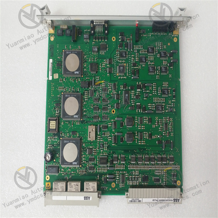
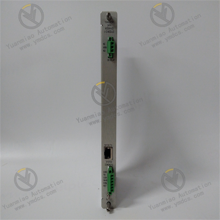
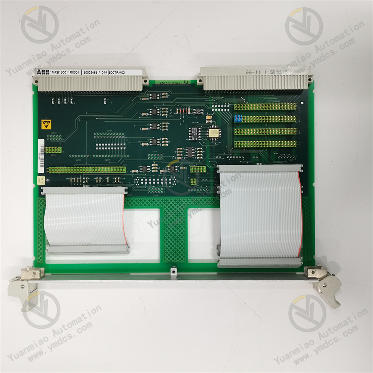
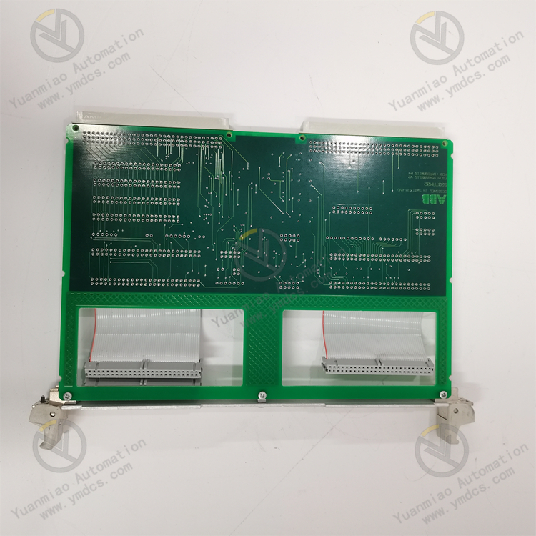
ABB 500TRM02 1MRB150011R0001
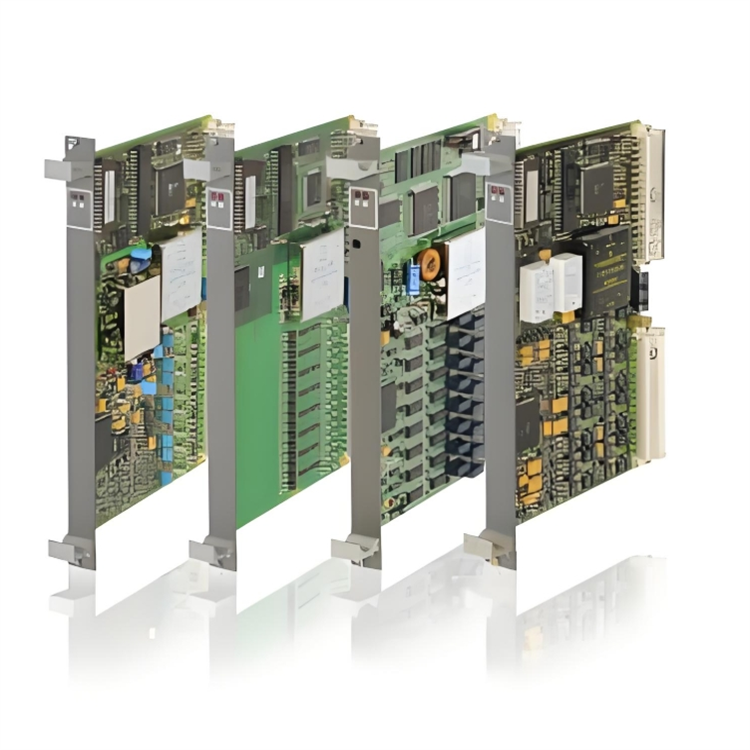
ABB 500TRM02 1MRB150011R0001 is a coupler module primarily used in industrial automation systems, with the following functional characteristics:
Functional Features
Powerful Communication Capability
- Supports multiple fieldbus protocols such as Profibus-DP and Modbus-RTU, enabling integration with different control systems.
- Enables high-speed data transmission, with a communication rate of up to 12Mbps (Profibus-DP), meeting the high real-time requirements of industrial automation systems.
Strong Module Expansion Capability
- Each coupler can support up to 64 modules (depending on fieldbus load), facilitating system expansion according to actual needs.
- Capable of connecting multiple input/output modules to achieve large-scale industrial control.
Adaptability to Multiple Signal Types
- Can connect to various module types, including Digital Input (DI), Digital Output (DO), Analog Input (AI), and Analog Output (AO).
- Adapts to the connection of various sensors and actuators, meeting signal processing requirements in different industrial control scenarios.
Diagnostic and Protection Functions
- Features fault alarm and self-diagnosis functions to promptly detect and resolve issues.
- Provides protection against faults such as overcurrent, overvoltage, undervoltage, and short circuits, ensuring the safe operation of equipment and systems.
Strong Work Environment Adaptability
- Operating temperature range: -25°C to +60°C (industrial grade, no derating required).
- Humidity ≤95% (non-condensing), capable of withstanding certain vibrations/shocks, compliant with IEC 60068-2-6 standards, and adaptable to harsh industrial environments.
Convenient Installation and Maintenance
- Installed via DIN rail (TS 35/7.5/15) for quick and easy installation, maintenance, and module replacement.
- Compact design with small footprint, facilitating installation in various industrial control cabinets.
Technical Parameters
Electrical Parameters
- Nominal operating voltage: 24V DC (with a certain allowable voltage range) to ensure stable power supply for the module's normal operation.
- Low-power design reduces energy consumption and overall system power consumption while maintaining effective operation.
Communication Parameters
- Supports multiple fieldbus protocols (e.g., Profibus-DP, Modbus-RTU) for easy integration with different control systems, enabling fast and accurate data transmission.
- High communication rates meet the real-time requirements of industrial automation systems (e.g., up to 12Mbps for Profibus-DP), ensuring timely processing and transmission of large volumes of data.
I/O Points
- Features multiple input/output points, with specific quantities varying by actual configuration (commonly 16-point, 32-point, etc.), meeting industrial control needs of different scales.
- Rich input/output signal types include DI, DO, AI, and AO, adapting to the connection of various sensors and actuators.
Protection Level
- The enclosure protection level typically reaches IP20 or higher, preventing the intrusion of objects larger than 12.5mm (e.g., fingers or similar objects), ensuring safety and stability in general industrial environments.
- In some special applications, it may have a higher protection level (e.g., IP65), suitable for harsher environments such as dusty or water-splashing sites.
General Operation Guide for ABB 500TRM02 1MRB150011R0001
Installation Preparation
- Confirm that the installation environment meets requirements: operating temperature -25°C to +60°C, humidity ≤95% (non-condensing).
- Prepare DIN rail (TS 35/7.5/15) and relevant installation tools.
Installation Steps
- Smoothly clip the coupler module onto the DIN rail to ensure secure installation.
- Connect relevant power cables, communication cables, and I/O module cables according to the manual, ensuring correct and secure wiring to avoid loose connections or short circuits.
Communication Settings
- Set the coupler's communication parameters (e.g., select the corresponding fieldbus protocol: Profibus-DP, Modbus-RTU) via DIP switches or software configuration, and set communication rate, station address, etc.
- Ensure communication parameters match those of the main control system or other slave devices to enable normal data transmission.
I/O Module Configuration
- Correctly connect corresponding I/O modules (DI, DO, AI, AO) to the coupler according to control requirements.
- For configurable I/O modules, set input/output types, range limits, and other parameters via software or DIP switches.
System Debugging
- After powering on, observe the status indicators of the coupler and modules to confirm normal power-up.
- Send test commands via the main control system or debugging tools to check data transmission between the coupler and I/O modules, as well as the accuracy of I/O module responses to input signals and control of output signals.
- Perform simple functional tests (e.g., simulating changes in input signals and observing whether corresponding output signals change as expected) to verify the overall system functionality.
Operation and Monitoring
- Regularly check the operating status of the coupler and modules (including temperature, indicator status, etc.) during system operation to ensure they operate under normal conditions.
- Monitor input/output data of I/O modules and system operating status in real time via the main control system or monitoring software, and promptly identify and address abnormal conditions.
How to Solve Common Issues in the Operation Guide for ABB 500TRM02 1MRB150011R0001
1. Communication Failures
Common Symptoms
- The module cannot communicate with the main controller/slave devices (indicator lights off or flashing abnormally).
- Data transmission delays, packet loss, or high error rates.
Possible Causes and Solutions
- Power Issues
- Cause: Unstable power supply voltage, loose wiring, or incorrect power specifications (e.g., non-24V DC).
- Solution:
- Measure the power supply voltage with a multimeter to ensure it is within the rated range (typically 24V DC ±10%).
- Check power terminal connections, re-plug or tighten cables to avoid loose connections.
- Incorrect Communication Parameter Configuration
- Cause: Station address conflicts, mismatched baud rate/protocol, or incorrect parity settings.
- Solution:
- Reset the station address via module DIP switches or configuration software (e.g., ABB Control Builder) to ensure uniqueness and consistency with the system.
- Verify communication protocols (e.g., Profibus-DP/Modbus-RTU), baud rates (e.g., 12Mbps), and parity settings to fully match the master device.
- Communication Cable or Interface Faults
- Cause: Damaged cables, poor connector contact, or interference due to improper grounding.
- Solution:
- Replace with shielded twisted-pair cables (meeting fieldbus standards), check cable connectors for tightness, and re-terminate if necessary.
- Ensure communication cables are routed independently, away from power cables, and the module is reliably grounded (ground resistance <10Ω).
- Module or Master Device Faults
- Cause: Hardware damage to the module or faulty communication ports on the master controller.
- Solution:
- Test with a spare module; if functional, the original module needs factory repair.
- Test the master controller's port with other slave devices to rule out master device issues.
2. Unresponsive or Abnormal I/O Modules
Common Symptoms
- No signal feedback from input modules (e.g., DI indicator off).
- Output modules cannot control devices (e.g., DO contacts not actuating).
- Large deviations in analog signals (e.g., AI displayed values inconsistent with actual values).
Possible Causes and Solutions
- Incorrect or Loose Wiring
- Cause: Reversed signal wires, incorrect terminal wiring, or loose terminal screws.
- Solution:
- Refer to the module manual to confirm input/output types (e.g., DI/DO/AI/AO) and terminal numbers, then rewire.
- Inspect each terminal to ensure cables are securely inserted and screws are tightened.
- Mismatched Signal Types with Modules
- Cause: Input signals exceed module ranges (e.g., AI module configured for 4-20mA but receiving 0-10V signals).
- Solution:
- Set the correct signal type (e.g., voltage/current, range) via module DIP switches or software configuration.
- For analog modules, calibrate zero and span (if needed, use calibration tools per the manual).
- Load Issues (Output Modules)
- Cause: Load current exceeds module ratings, triggering overload protection.
- Solution:
- Check the module manual for maximum output channel loads (e.g., DO contact capacity: 2A/250V AC), and replace with suitable relays or contactors.
- For inductive loads, parallel surge suppressors (e.g., RC circuits or diodes) to prevent back EMF from damaging modules.
- Module Channel Faults
- Cause: Damaged individual channels or internal circuit failures.
- Solution:
- Switch to spare channels and reconfigure signal paths.
- If all channels are abnormal, replace the module and reconfigure.
3. Module Overheating or Abnormal Indicator Lights
Common Symptoms
- Excessive module temperature, hot surface.
- Power indicator (PWR) off or flashing, fault indicator (FAULT) constantly on.
Possible Causes and Solutions
- Poor Heat Dissipation
- Cause: Inadequate ventilation in the installation environment, too close module spacing, or severe dust accumulation.
- Solution:
- Ensure at least 25mm spacing between modules for heat dissipation, and install in a well-ventilated control cabinet.
- Regularly clean module surfaces and rails to prevent dust from blocking cooling vents.
- Overload or Short Circuit
- Cause: I/O channel short circuits or power overload triggering module protection.
- Solution:
- Disconnect all external loads and troubleshoot short circuits one by one (e.g., damaged output circuit wires).
- Check power supply capacity to ensure it meets the total power consumption of the module and all I/O modules (refer to manual power parameters).
- Firmware Version Issues
- Cause: Outdated module firmware with compatibility bugs.
- Solution:
- Download the latest firmware via ABB official tools (e.g., DriveWindow) and upgrade the module per the guide.
- Backup configuration data before upgrading to avoid loss.
4. System Compatibility Issues
Common Symptoms
- Module cannot communicate with third-party devices (e.g., non-ABB controllers).
- Number of extended modules exceeds bus load limits.
Possible Causes and Solutions
- Insufficient Protocol Compatibility
- Cause: Third-party devices do not support the module's native protocol (e.g., only Modbus TCP supported while the module uses Modbus-RTU).
- Solution:
- Use protocol gateways (e.g., Modbus RTU to TCP gateways) for protocol conversion.
- Ensure third-party devices support the module's communication protocol and open corresponding communication interface permissions.
- Excessive Bus Load
- Cause: The number of connected I/O modules exceeds the coupler's maximum support (e.g., >64 modules).
Solution:
- Reduce the number of modules or split the system into multiple subnets, expanding bus capacity via repeaters.
- Optimize communication parameters (e.g., lower baud rate) to reduce bus load.