Description
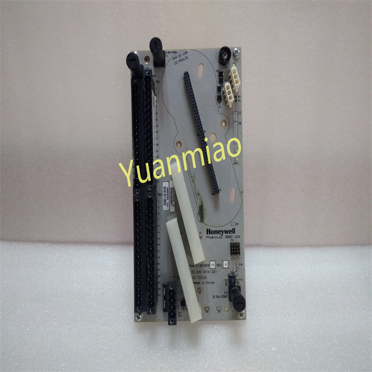
GE IS200TRPGH1BDD
Technical Parameters
Electrical Parameters
◦ Operating Voltage: Typically, the operating voltage for this type of GE module is 24V DC. For example, the IS200TRLYH1BGF module is powered by 24V DC. However, there are exceptions such as the IS200TPROH1BCB module, which operates at 52V, though this is relatively rare.
◦ Output Current: If the module has analog output functionality, the output current range is likely 4–20mA. For instance, the IS200TRLYH1BGF module outputs 4–20mA.
◦ Output Current: If the module has analog output functionality, the output current range is likely 4–20mA. For instance, the IS200TRLYH1BGF module outputs 4–20mA.
Functional Parameters
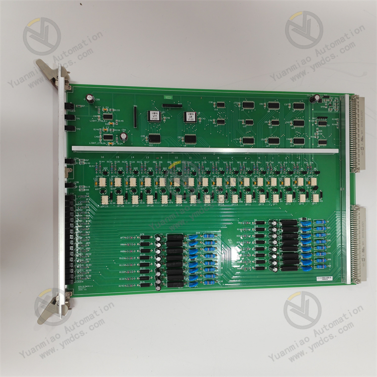
◦ I/O Channels: Referencing the IS200TRPAH1AFC module, which has 16 input and 16 output channels, the IS200TRPGH1BDD module may have a similar channel configuration, though other configurations (e.g., 8 inputs and 8 outputs) are also possible.
◦ Communication Protocols: Likely supports common protocols such as Modbus RTU and Ethernet/IP for data interaction with other devices. For example, the IS200TRPAH1AFC module supports both Modbus RTU and Ethernet/IP.
◦ Communication Protocols: Likely supports common protocols such as Modbus RTU and Ethernet/IP for data interaction with other devices. For example, the IS200TRPAH1AFC module supports both Modbus RTU and Ethernet/IP.
Mechanical Parameters
◦ Dimensions and Weight: The IS200TRPGH1B module measures 45cm×35cm×32cm and weighs 2kg. The IS200TRPGH1BDD module is expected to have similar dimensions and weight.
Environmental Parameters
◦ Operating Temperature Range: GE industrial modules generally operate within a wide temperature range. For example, the IS200TRPAH1AFC module functions between -40°C and +70°C, and the IS200TRPGH1BDD module likely operates within a similar range.
Functional Features
Relay and Trip Control
As a primary trip terminal board, it features three voting circuits connected to three trip solenoids via nine magnetic relays. This enables reliable control of trip operations, ensuring accurate triggering of trips when needed to safeguard the safe operation of gas turbines.
Multi-Signal Processing
- Accepts input signals from eight Geiger-Müller flame detectors to monitor the combustion status of gas turbines, providing critical flame detection information to the control system.
- Manages voltage supply for relay coils and voltage/current supply for flame detectors, processing and transmitting various signal types to meet the interactive needs of multiple signals in gas turbine control systems.
Interfaces and Compatibility
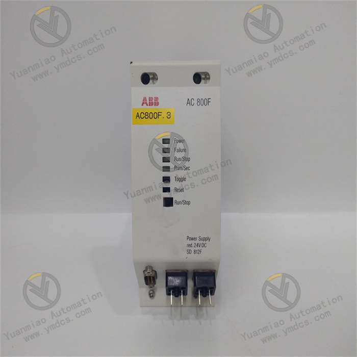
- In the Mark VI system, it connects to the VTUR board via a cable with a molded plug to the VME rack where the VTUR board is installed.
- In the Mark VIe system, it is controlled by the PTUR component on TTURH1C, which accepts I/O components as inputs via a D-type connector. It supports simplex and triple modular redundancy (TMR) systems, offering strong compatibility with different system architectures and application scenarios.
Working Principle
I. Module Positioning and Core Functions
Application Scenario: As a key component of the Mark VIe system, this module primarily monitors and controls the rotational speed of gas turbines, ensuring stable speed during startup, operation, and shutdown, while providing safety functions such as overspeed protection.
Core Functions:
Core Functions:
- Acquires raw signals from rotational speed sensors (e.g., reluctance sensors).
- Filters, amplifies, and digitizes signals to calculate real-time rotational speed values.
- Communicates with other control system modules (e.g., main control modules, protection modules) to transmit speed data or control commands.
- Supports redundant configurations to enhance system reliability (in some models or setups).
II. Detailed Working Principle
- Signal Acquisition and Preprocessing
- Filtering: Removes high-frequency noise via hardware filters (e.g., RC filter circuits) to avoid interference with speed calculations.
- Amplification and Shaping: Amplifies weak AC signals and converts them into square waves via Schmitt triggers for subsequent digital circuit processing.
- Input Signal Type: Receives AC voltage signals from rotational speed sensors (frequency proportional to speed), such as sinusoidal signals from reluctance sensors. The frequency formula is:f=60n×p
(where n = rotational speed, p = number of teeth on the sensor gear). - Signal Conditioning:
- Speed Calculation and Digitization
- Measuring a single period T, rotational speed n=T×p60.
- Counting pulses within a fixed time window to calculate frequency.
- Frequency Measurement: Measures the period or frequency of square wave signals using counter chips (e.g., FPGA or specialized timing chips). For example:
- Digitization: Converts calculated speed values into digital signals (e.g., 16-bit binary numbers) and transmits them to the main control module via an internal bus (e.g., VME bus).
- Control Logic and Protection Functions
- Closed-Loop Control Logic: Adjusts actuator signals (e.g., fuel valves) using preset control strategies (e.g., PID control) based on speed feedback and target values to regulate unit speed.
- Overspeed Protection: Immediately triggers a hardware trip signal via hardwired connections to shut down solenoids when speed exceeds a set threshold (e.g., 110% of rated speed), ensuring safe shutdown independent of software logic ("fail-safe" mechanism).
- Communication and Redundancy Mechanisms
- Data Communication: Exchanges data with other modules via serial interfaces (e.g., RS-485) or buses (e.g., Ethernet), such as sending real-time speed data to HMIs or receiving control parameters from main control modules.
- Redundancy Design (Partial Configurations): Employs dual-module redundancy, where two modules operate simultaneously and cross-verify data. If the primary module fails, the backup module switches over to control, preventing single-point failures.
III. Key Technical Points
- Anti-Interference Design: Uses isolated power supplies and shielded circuits to reduce EMI effects on signal acquisition. Hardware watchdog circuits prevent program crashes to ensure stable operation.
- High-Precision Measurement: Counter resolution reaches nanosecond levels to ensure speed calculation accuracy (e.g., ±0.1% error). Supports multi-channel inputs (e.g., three speed sensors) with a two-out-of-three voting mechanism for reliability (compliant with SIL safety standards).
- Real-Time Performance and Response Speed: Signal processing cycles are short (typically <10ms) to meet fast adjustment needs of gas turbines. Hardware-triggered overspeed protection signals respond in microseconds for emergency shutdowns.
IV. Coordination with Other System Components
- Sensor Connection: Receives speed sensor signals via a dedicated terminal board with overvoltage protection and signal isolation.
- Actuator Interaction: Outputs analog signals (e.g., 4–20mA) to fuel control systems or digital signals to variable frequency drives (VFDs).
- Integration with Protection Systems: Overspeed signals are also fed into independent protection modules (e.g., GE’s UR6ES module) for dual protection.
V. Typical Application Process
- Startup Phase: Acquires starter motor speed to determine if ignition speed thresholds are met. After ignition, adjusts speed to no-load speed (e.g., 3000rpm) in real time as fuel increases.
- Grid-Connected Operation Phase: Adjusts fuel supply via speed control loops based on grid frequency signals to maintain synchronous speed with the grid.
- Shutdown Phase: Gradually reduces fuel supply after receiving shutdown commands, continuously monitoring speed until the unit stops completely.

Fault Diagnosis and Troubleshooting for IS200TRPGH1BDD Module
I. Preparation for Fault Diagnosis
- Confirm Module Function and System Architecture: Clarify the module’s role (e.g., I/O module, communication module, control module) and refer to official manuals for baseline information such as indicator light statuses, voltage ranges, and communication protocols.
- Safety Precautions: Ensure physical inspections are conducted with power off or isolated to avoid electric shock or equipment damage. Wear anti-static wristbands to prevent electrostatic damage to components.
II. Initial Visual and Hardware Checks
- Visual Inspection:
- Look for physical damage (cracks, burn marks, bulging capacitors) on the module casing.
- Check terminal blocks, cable interfaces, and slots for loose connections, oxidation, corrosion, or poor contact.
- Verify module model, firmware version, and compatibility with the system to determine if an upgrade is needed.
- Power and Voltage Test: Measure the module’s supply voltage (e.g., DC 24V or AC 110V) with a multimeter to ensure it falls within the nominal range (±5% error). If voltage is abnormal, check upstream power modules or supply lines.
III. Indicator Light Status Analysis (Key Diagnostic Tool)
Common indicator light meanings (subject to actual module specifications):
| Indicator | Normal Status | Abnormal Status and Possible Causes |
|---|---|---|
| PWR (Power) | Steady green | Off: Power failure, module damage, or blown fuse. |
| RUN (Operation) | Periodic green flash | Off or steady: Module initialization failure, firmware fault. |
| FAULT (Fault) | Off | Steady red: Internal fault, overload, communication interrupt, or parameter error. |
| COM (Communication) | Flashing green | Off or steady: Communication line fault, address conflict, or protocol error. |
| I/O Status Lights | Change with signal I/O | No change: Signal source fault, terminal poor contact, or module channel damage. |
Actions: Record the combination of indicator lights during a fault and refer to the manual to determine the fault type (e.g., communication fault, hardware fault, or software anomaly). If the FAULT light is on, try rebooting the module (power off for 30 seconds before restarting) to see if it resolves.
IV. Functional Testing and Signal Verification
- I/O Testing:
- Analog Input (AI): Connect a standard signal source (e.g., 4–20mA or 0–10V) and read values via control system software to compare with actual inputs (allowable error: ±1%). If abnormal, check the signal source, cable shielding, grounding, or replace the channel for testing.
- Analog Output (AO): Send commands via software and measure voltage/current at module output terminals to confirm matching. Abnormal outputs may indicate internal driver circuit faults, requiring module replacement.
- Digital Input/Output (DI/DO): Manually trigger input signals (e.g., pushbuttons) to observe indicator lights or system status changes. For outputs, test relay contact actuation with a multimeter’s continuity function.
- Communication Testing: Use an oscilloscope or specialized tools to detect signal waveforms and levels on the communication bus (e.g., RS-485, Ethernet) for interference or attenuation. Check module address settings, baud rate, and parity bits for consistency with the system, and try replacing communication cables or interface modules.
- Load Testing: If the module drives external devices (e.g., solenoids, motors), check for overloads (current exceeding rated values) causing overheating or protection activation. Measure module surface temperature; if excessively hot (e.g., >60°C), suspect poor heat dissipation or component aging.
V. System-Level Diagnosis and Software Troubleshooting
- Control System Log Analysis: Review fault logs from the host computer or PLC to obtain module-related error codes (e.g., "communication timeout," "channel fault"). Use the codes to locate faults in the manual (e.g., software configuration errors, firmware defects, or compatibility issues).
- Firmware Upgrade and Configuration Reset: Confirm if the module’s firmware is up-to-date and upgrade it via official procedures if known bugs exist. Attempt to restore factory settings (via hardware jumpers or software commands) and retest after reconfiguring parameters.
- Swap Testing: Safely swap the faulty module with a known-good identical module to observe if the fault transfers. If it does, the module is damaged and needs repair/replacement. If not, check slot contact issues, backplane bus faults, or system power problems.
VI. Common Faults and Solutions
| Fault Symptom | Possible Causes | Solutions |
|---|---|---|
| No power indication | Power failure, blown fuse, internal power circuit damage | Check power input, replace fuse or module. |
| Communication interrupt | Damaged cable, faulty interface chip, address conflict | Replace cable, reset address, or replace communication module. |
| Abnormal I/O signals | Damaged channel, loose terminal, external interference | Clean terminals, check shielding/grounding, replace channel or module. |
| Frequent fault codes | Firmware defects, parameter errors, environmental interference | Upgrade firmware, reset parameters, improve EMI environment (e.g., keep away from inverters). |
| Module overheating | Poor heat dissipation, overload, component aging | Clean cooling vents, |