Description
DS215SDCCG1AZZ01A
I. Overview
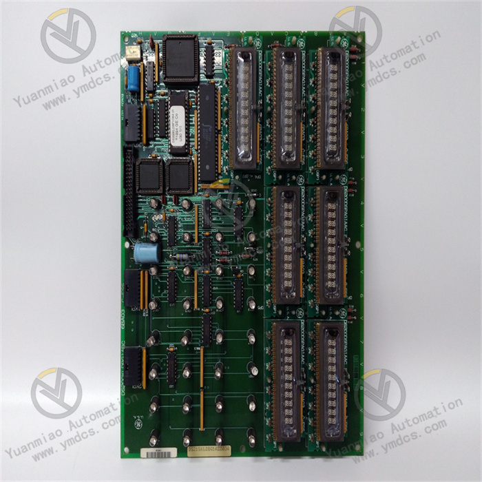
GE DS215SDCCG1AZZ01A is a drive control card meticulously crafted by General Electric (GE) for the Mark V series control boards. As the core of the turbine control system, the Mark V series is widely applied in management and control systems for automation drive components of wind, steam, and gas turbines. Although this series has become an obsolete legacy product and was discontinued years after GE's initial release, it remains noted due to its adoption of the patented Speedtronic control system technology, which first debuted with the Mark I series in the mid-to-late 1960s.
DS215SDCCG1AZZ01A optimizes the performance specifications and dimensions of the basic version through Class A functional product revisions and optional software packages. As a special mainboard component, it distinguishes itself from smaller card products in the ordinary Mark V series. It carries the main control circuit and system software, playing a key role in drive applications for AC 2000, DC 2000, and EX2000 series drivers.
II. Functional Features
- Powerful Microprocessor Collaboration: The board integrates three microprocessors: Drive Control Processor (DCP), Motor Control Processor (MCP), and Co-Motor Processor (CMP).
- DCP handles peripheral functions, analog/digital I/O, and executes programs like address decoders, wait state generators, and interrupt controllers.
- MCP undertakes motor control and system I/O functions. When MCP's processing capacity is insufficient for control algorithms, CMP takes over, offering extra processing power for complex mathematical calculations.
- Efficient Data Storage and Interaction: Equipped with dual-port Random Access Memory (RAM), supporting independent and simultaneous access to the same memory array by microprocessors for efficient data sharing. Storage space is integrated in five drive chips: four EPROMs (U11, U12, U22, U23) store factory-programmed configuration data, and one EEPROM (U9) stores field-adjustable parameters. All chips are socket-mounted for easy replacement and maintenance.
- Convenient Fault Diagnosis: A set of ten on-board LEDs displays fault codes in Binary Coded Decimal (BCD) or binary format, enabling users to quickly locate and troubleshoot faults, improving maintenance efficiency.
- Diverse Interface Configurations:
- 1PL interface serves as a bidirectional I/O channel between the power/interface board (IMCP, DCI, SDCI, or DCFB) and SDCC for efficient key instruction and information interaction.
- 2PL interface transmits ±5V, 15V, and 24V DC input voltages from the power/interface board to supply stable power for SDCC.
- 3PL interface directs outputs to the LAN communication card, facilitating data exchange and control between SDCC and the LAN.
- 6PL and 8PL interfaces establish communication between the drive terminal board or simple drive terminal board and SDCC, ensuring communication and control coordination between key components.
- 7PL interface (in applicable configurations) enables communication between the signal processor card or multi-bridge signal processing card and SDCC, enhancing overall system functionality.
- 11PL interface directs SDCC outputs to instruments, providing a pathway for data visualization and measurement.
- Flexible Hardware Configuration: Features Berg-type hardware jumpers (named JP) and hard-wired jumpers (named WJ) for flexible configuration per actual application scenarios. On-board test points, composed of metal posts arranged along specific signal paths, allow convenient signal measurement/observation via tools like oscilloscopes for testing and troubleshooting.
III. Technical Parameters
- Input Voltage: Supports ±5V, 15V, and 24V DC inputs, adapting to various power scenarios for stable power supply.
- Operating Temperature Range: (To be supplemented based on the actual product, not mentioned in the document). Presumed to have industrial-grade temperature adaptability for different working environments.
- Storage Temperature Range: (To be supplemented based on the actual product, not mentioned in the document). Ensures reliability during non-operational storage.
- Dimensions: 16cm×16cm×12cm. Compact design facilitates installation in control cabinets and equipment spaces.
- Weight: 0.8kg. Reasonable weight for easy installation and handling.
- Microprocessors: 3 × 16-bit microprocessors, collaborating to achieve powerful data processing and control.
- Memory: Integrates five storage chips (four EPROMs and one EEPROM) for data storage, paired with dual-port RAM for efficient data interaction.
- Fault Display: 10 on-board LEDs display fault codes in BCD or binary format.
- Interface Types: Includes 1PL, 2PL, 3PL, 6PL, 7PL, 8PL, 11PL, etc., meeting connection and communication needs for different devices.
- Jumper Types: Berg-type hardware jumpers (JP) and hard-wired jumpers (WJ) support hardware configuration adjustment.
- Test Points: On-board metal post test points for convenient signal measurement and troubleshooting.
IV. Working Principle
During operation of the entire drive control system, the Drive Control Processor (DCP) of DS215SDCCG1AZZ01A first performs preliminary processing on signals received from sensors, upper computers, etc. It converts analog signals to digital signals and preliminarily filters/classifies data according to preset programs. For example, in a motor drive system, sensors detect motor speed, current, etc., which DCP receives and processes.
Subsequently, the Motor Control Processor (MCP) performs real-time control of the motor's operating status based on DCP-processed data and the system's preset control algorithms. If complex working conditions occur (e.g., sudden load changes increasing control algorithm execution difficulty) and MCP's processing capacity is insufficient, the Co-Motor Processor (CMP) intervenes promptly. Leveraging its strong computing power, CMP executes complex mathematical calculations and replans control strategies to ensure stable motor operation.
In data storage and interaction, dual-port RAM plays a key role, allowing simultaneous read/write operations by different processors for fast data transfer and sharing among processors. Meanwhile, data in storage chips is updated in real-time based on system operating status, providing accurate configuration information and parameters for processors. When system faults occur, the fault detection circuit is triggered to generate corresponding fault codes, which are displayed via on-board LEDs in a specific coding format to prompt maintenance personnel for troubleshooting and repair.
V. Common Faults and Solutions
- Microprocessor Failure
- Fault Phenomenon: Abnormal 卡顿 (lag), incorrect control instruction execution, or unresponsiveness during device operation, possibly accompanied by abnormal LED fault light flashing.
- Solutions: First, read microprocessor operation logs and error codes via professional detection equipment to identify the faulty microprocessor. For software issues, attempt to reprogram or reset microprocessor parameters; for hardware damage (e.g., overheated/burned chips), contact professionals to replace the corresponding microprocessor chip.
- Data Storage Anomaly
- Fault Phenomenon: The system cannot read/write data in storage chips normally, leading to loss of device operation parameters, configuration errors, and impaired normal operation.
- Solutions: Check storage chip power supply and interface tightness. If normal, use specialized storage chip detection tools to test the chips. For logical errors, attempt data repair; for physical damage, replace with the same model chip and reprogram correct configuration data/parameters.
- Interface Communication Failure
- Fault Phenomenon: Interfaces connected to other devices fail to communicate normally (e.g., data transmission interruptions, severe packet loss), causing abnormal data interaction and collaborative work issues between systems.
- Solutions: Carefully inspect interface connection cables for damage/looseness, and re-plug to ensure firm connection. Check if interface communication protocol settings match connected devices; if not, reconfigure protocol parameters. If unresolved, it may be a hardware fault in the interface circuit. Use circuit detection instruments to locate and repair fault points, or replace the interface circuit module if necessary.
- Abnormal LED Fault Display
- Fault Phenomenon: LEDs do not light up or display fault codes inconsistent with actual faults, failing to provide accurate fault information and increasing troubleshooting difficulty.
- Solutions: Check LED power supply circuit. If normal, the LED lamp bead may be damaged—replace it directly. If the displayed code is incorrect, inspect the fault detection circuit for short circuits/open circuits, etc., and repair it to ensure accurate fault detection and code output to the LED.