Description
Part Number: IS220PDOAH1A
Manufacturer: General Electric
Series: Mark VIe
Product Type: Discrete Output Pack
Size: 8.26 cm high x 4.19 cm wide x 12.1 cm deep
Technology: Surface-mount
Relay and coil monitoring: 15 pack inputs
Number of relay channels: 12
Country of Manufacturer: United States (USA)
Functional Description
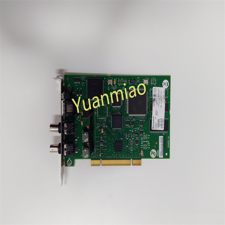
IS220PDOAH1A is a Discrete Output Pack developed by General Electrics. It is a part of Mark VIe control system. PDOA serves as the crucial link in the electrical connection between one or two Input/Output (I/O) Ethernet networks and a dedicated discrete output terminal board. This essential component consists of two key elements- a processor board that is common to all Mark VIe distributed I/O packs, and an acquisition board that is tailored to the specific requirements of discrete output functionalities. It is designed to enable the control of up to 12 relays while also facilitating feedback integration from the terminal board.
Features
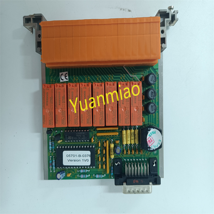
- In terms of relay options, users have the flexibility to choose between electromagnetic relays, which are compatible with various terminal boards (TRLYH1B, C, D, and F), and solid-state relays, which can be utilized with type TRLYH1E boards. This diversity in relay options allows for customization to meet the specific needs of the application.
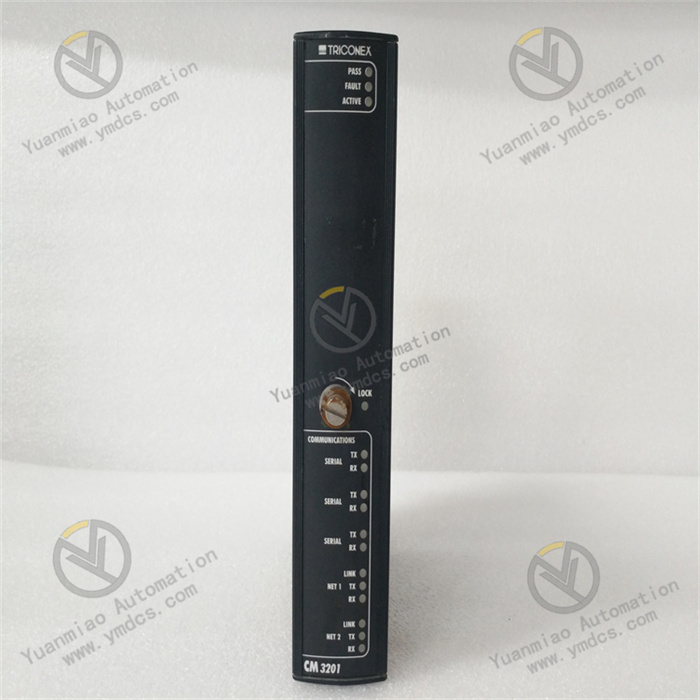
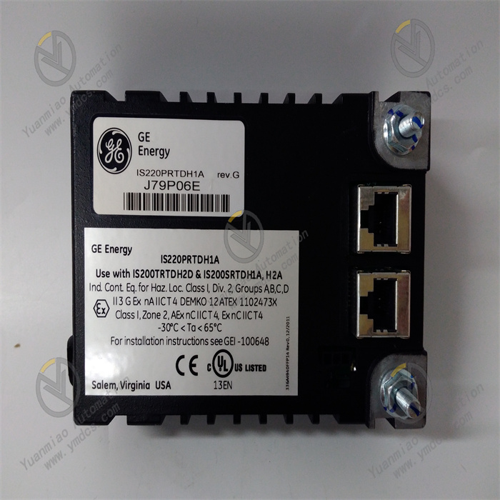
- Input connectivity is established through dual RJ45 Ethernet connectors, providing a reliable and redundant interface for seamless data exchange. Furthermore, power is supplied through a three-pin input, ensuring stable and efficient operation. On the output side, the PDOA is equipped with a DC-37 pin connector that seamlessly connects with the corresponding terminal board connector. This connection mechanism simplifies installation and maintenance processes.
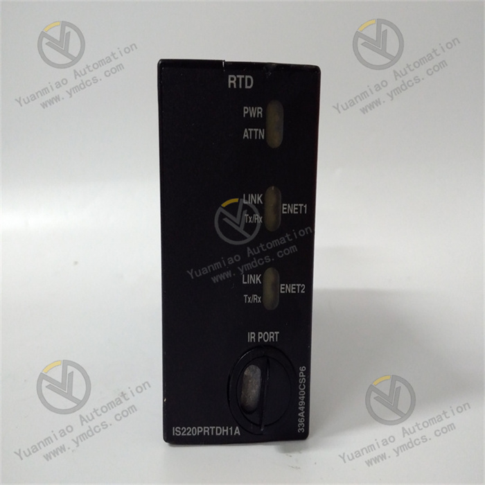
- To aid in monitoring and troubleshooting, the component is equipped with indicator LEDs that offer visual diagnostics, allowing users to quickly assess the status and performance of the system. Additionally, for more in-depth diagnostic and configuration tasks, local serial communications can be established through an infrared port, providing a convenient means of interaction with the PDOA.
Installation
- Begin by securely mounting the terminal board of your choice in the desired location.
- For a simplex configuration, connect one PDOA I/O pack to the terminal board connector. In the case of a TMR (Triple Modular Redundant) setup, connect three PDOA I/O packs to the terminal board connectors.
- To ensure mechanical stability, secure the packs by utilizing the threaded studs located adjacent to the Ethernet ports. These studs should be inserted into a specific mounting bracket tailored to the terminal board type. Adjust the bracket's position to prevent any right-angle force exerted on the DC37 connector between the pack and the terminal board. This adjustment is typically a one-time requirement throughout the product's lifespan.
- Depending on your system configuration, plug in one or two Ethernet cables. The PDOA pack is capable of operating seamlessly using either port. If you opt for a dual connection, it is standard practice to connect ENET1 to the network associated with the R controller.
- Apply power to the pack by connecting the power connector located on the side of the pack. It is not necessary to insert this connector with the power removed from the cable since the I/O pack features built-in soft-start capability, which effectively manages the current inrush when power is applied.
Configure the I/O pack according to your specific requirements. This step ensures that the PDOA pack functions optimally within your application.
Processor
- High-Speed Processor Equipped with RAM and Flash Memory: A high-performance processor boasting sufficient RAM and flash memory for efficient data processing and storage.
- Dual Independent 10/100 Ethernet Ports with Connectors: Two fully autonomous Ethernet ports with compatible connectors, ensuring reliable and rapid network connectivity.
- Hardware Watchdog Timer and Reset Circuit: Built-in hardware watchdog timer and reset circuitry for system reliability, ensuring continuous operation and swift recovery in case of issues.
- Local Ambient Temperature Sensor: An onboard sensor that monitors the local ambient temperature, facilitating environmental monitoring and control.
- Infrared Serial Communications Port: An infrared serial communications port, enabling local diagnostic and configuration tasks through wireless connectivity.
- Status-Indication LEDs: Status-indication LEDs that provide visual feedback, allowing users to assess the operational status of the processor board.
- Electronic ID and ID Reading Capability: Electronic identification for the processor board, as well as the ability to read identification information from other boards, streamlining system management.
- Extensive Programmable Logic Support for the Acquisition Board: Substantial programmable logic capabilities to support and enhance the functionality of the acquisition board, enabling customization for specific applications.
- Input Power Connector with Soft Start/Current Limiter: A dedicated input power connector featuring soft start and current limiting mechanisms, ensuring controlled and safe power delivery.
- Local Power Supplies with Sequencing and Monitoring: Local power supplies equipped with sequencing and monitoring features, promoting efficient power management and system stability.
Installation
Configuration
Operation and Monitoring