Description
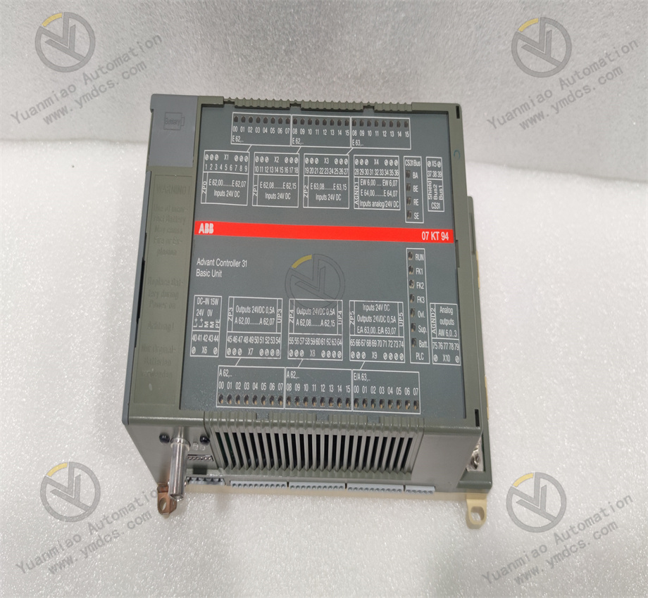
ABB 07KT94 GJR5252100R3261
I. Basic Information
- Full Model: 07KT94 GJR5252100R3261
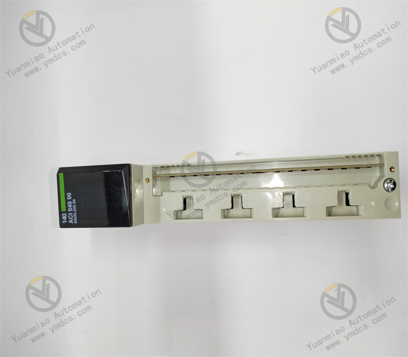
- Series: ABB industrial automation control module, belonging to digital input/output (DI/DO) modules, commonly used in AC 500 series PLCs or similar control systems.
- Purpose: As a digital signal processing unit in industrial automation systems, it connects devices such as switches, relays, and solenoid valves to achieve logical control and status feedback. It is suitable for discrete control scenarios in manufacturing, energy, infrastructure, and other fields.
II. Core Functions and Features
Digital I/O Capability
- Channel Configuration: Typically supports 16 digital input (DI) channels or 16 digital output (DO) channels, or mixed configuration (e.g., 8DI+8DO), subject to the manual.
- Signal Types:
- DI: Supports dry/wet contact (e.g., 24V DC signal) input, compatible with mechanical switches, proximity sensors, etc.
- DO: Relay output (contact capacity typically 2A/250V AC or 3A/30V DC) or transistor output (e.g., 24V DC/0.5A).
- Isolation Characteristics: Electrical isolation between channels (opto-coupler or relay isolation), isolation voltage ≥500V AC to prevent interference spread.
Electrical Characteristics and Protection
- Input Characteristics: Logic "1" input voltage range is typically 15-30V DC (wet contact), response time ≤10ms.
- Output Characteristics: Relay output supports inductive loads (e.g., solenoid valves) with a service life ≥10^6 operations; transistor output features fast response (≤1ms), suitable for high-frequency switching.
- Anti-Interference Design: Built-in filter circuit, supports resistance to electromagnetic interference (EMI) and radio-frequency interference (RFI), compliant with industrial environment standards.
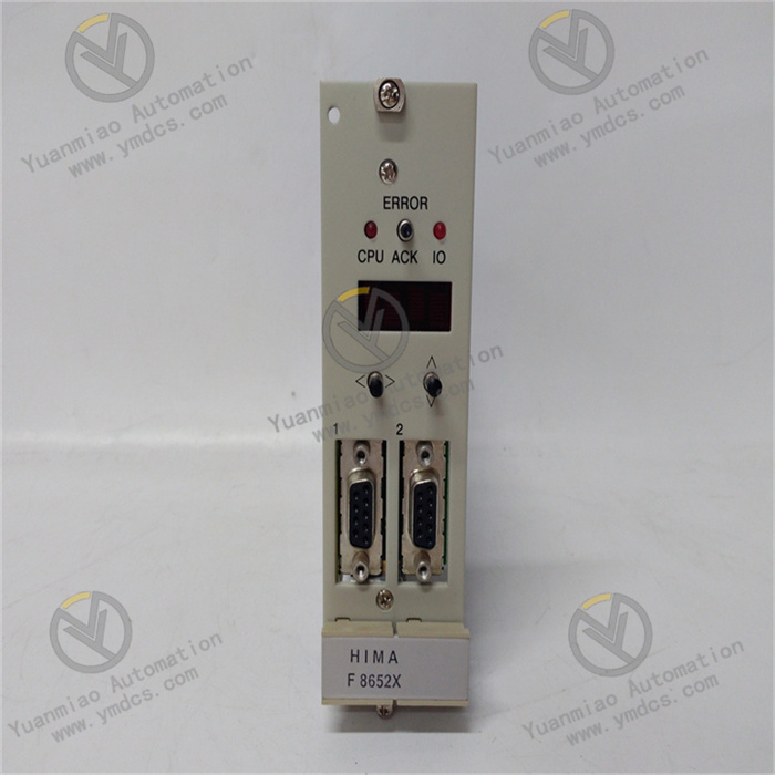
Diagnosis and Status Indication
- LED Indicators: Each channel is equipped with status indicators (ON/OFF) for intuitive signal status display; module-level indicators (PWR, FAULT) show power and fault status.
- Fault Detection: Supports channel-level short-circuit and overload detection, automatically cutting off output and alarming in case of faults.
III. Technical Parameters
| Parameter Dimension | Specific Indicators |
|---|---|
| Number of Channels | 16 DI or 16 DO channels (or mixed configuration) |
| Input Type | Dry/wet contact (24V DC), input impedance ≥4.7kΩ |
| Output Type | Relay output (2A/250V AC) or transistor output (24V DC/0.5A) |
| Response Time | DI: ≤10ms; DO (relay): ≤10ms, DO (transistor): ≤1ms |
| Operating Voltage | DC 24V (±10%), power consumption ≤5W |
| Operating Temperature | -20℃~+60℃ (industrial grade), humidity 5%~95% (non-condensing) |
IV. Application Scenarios
Manufacturing Automation
- Start/stop control of production lines (e.g., conveyor belts, robot workstations), collecting button signals via DI and driving contactors via DO.
- Equipment status monitoring (e.g., motor running/stopped, valve switch position), feeding back signals to PLC for logical judgment.
Energy and Power
- Control of circuit breaker switching in substations, controlling relays via DO output and collecting auxiliary contact status via DI.
- Equipment start/stop and status monitoring in new energy power generation (e.g., wind power, photovoltaics).
Infrastructure
- Lighting control and elevator status monitoring in building automation.
- Pump and valve control in wastewater treatment plants (e.g., grille decontamination machines, sludge pumps) for remote on/off control.
V. Installation and Usage Key Points
Installation Method
- Adopts DIN rail installation, requiring matching with AC 500 series racks or compatible PLC systems, ensuring module spacing ≥15mm for heat dissipation.
Wiring Specifications
- Use shielded cables for DI input signals to avoid long-distance transmission interference; when DO outputs inductive loads, connect freewheeling diodes in parallel (relay output) or RC snubber circuits (transistor output).
- Power wiring should use wires with cross-sectional area ≥1.5mm², grounding resistance ≤1Ω.
Configuration and Programming
- Use ABB Automation Builder or Control Builder F software to configure parameters such as I/O addresses, input filter time, and output types.
- Read DI status or control DO output via bit operation instructions (e.g., LD, OUT) in PLC programs.
Maintenance Notes
- Regularly check for loose terminal blocks (recommended to tighten every six months) to avoid faults caused by poor contact;
- If relay output contacts are severely worn (e.g., contact resistance >1Ω), replace the module in a timely manner;
- The module supports hot-swapping (for some models), but ensure no critical control tasks are executing during replacement.
VI. Comparison with Similar Products (vs Siemens S7-1200 DI/DO Module)
| Parameter Dimension | ABB 07KT94 | Siemens S7-1200 SM1222 |
|---|---|---|
| Number of Channels | 16 channels (optional DI/DO or mixed) | 8 DO (relay) or 16 DO (transistor) |
| Output Type | Relay/transistor optional | Model-specific selection (relay/transistor) |
| Isolation Voltage | 500V AC | 500V AC |
| Response Time | Relay ≤10ms, transistor ≤1ms | Relay ≤10ms, transistor ≤1ms |
| Applicable Systems | ABB AC 500 series | Siemens S7-1200 series |
VII. Typical Supporting Modules
- Controllers: ABB AC500 CPU (e.g., PM581), AC500-eCo CPU (economical type).
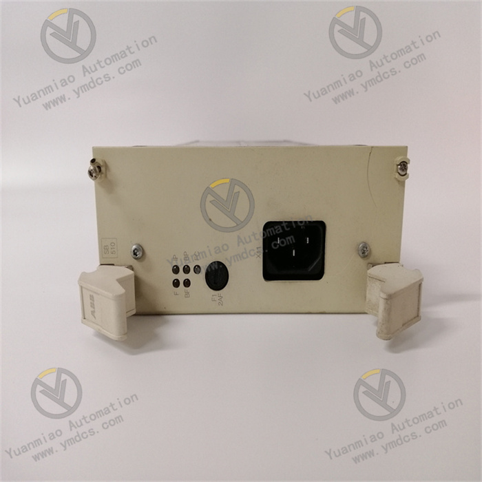
- Power Module: PS511 (DC 24V power supply) for powering I/O modules.
- Communication Modules: CM571 (Modbus RTU), CM572 (Profibus DP) for expanding communication capabilities.