Description
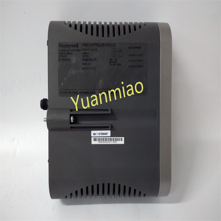
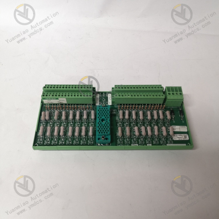
TRICONEX 9566-8XX Fault Tolerant Circuit Board
The 9566-810 is a key component of the Triconex TriStation Safety Instrumentation System (SIS), designed for safety-critical applications such as process control, power generation, and nuclear power plants. It stably and reliably collects digital input signals, supports connection to various sensors, and ensures the control system accurately receives and processes field device signals.
Product Features
- Digital Input Channels: Equipped with 32 digital input channels, capable of receiving digital signals from various sensors or field devices, supporting standard digital signal levels such as 24VDC or 125VDC.
- Signal Conditioning and Isolation: The terminal block integrates signal conditioning and isolation circuits to reduce signal interference and noise, enhancing system stability and reliability.
- Redundant Configuration: Supports redundant configuration, improving system fault tolerance and reliability through dual power supplies and processors. In redundant mode, the system can continue operating and monitoring/processing input signals even if one power supply or processor fails.
- Easy Installation and Maintenance: Terminal blocks are easy to install on DIN rails in control cabinets or panels for convenient installation and disassembly. Its modular design simplifies maintenance and replacement.
- Wide Operating Temperature Range: Can operate stably in temperatures ranging from -40°C to 70°C, adapting to various harsh industrial environments.
- Communication Protocols: Supports communication protocols such as Modbus, Ethernet, and OPC, facilitating integration and data exchange with other control systems and devices.
Technical Parameters (Taking Digital Input Module as an Example)
1. Channel Characteristics
- Number of Channels: Typically 16 or 32 channels (the specific meaning of the model suffix "8XX" needs confirmation; e.g., "832" may represent 32 channels).
- Signal Types:
- Supports Dry Contact or Wet Contact inputs.
- Input voltage range: Commonly 24V DC (±10%), with some models supporting 125V AC/DC.
- Isolation Characteristics:
- Electrical isolation between channels (isolation voltage typically 500V AC/DC).
- Isolation between the module and the system, resistant to electromagnetic interference (EMI) and radio frequency interference (RFI).
2. Electrical Characteristics
- Power Requirements:
- Supply voltage: 24V DC (typical value, may support wide voltage input such as 18-32V DC).
- Power consumption: Approximately 5-10W per module (specifically depends on the number of channels and functions).
- Input Impedance: High impedance in dry contact mode (e.g., ≥100kΩ), matching the corresponding voltage level in wet contact mode.
- Response Time:
- Adjustable filtering time (e.g., 1-100ms for anti-interference).
- Signal acquisition cycle: Meets Triconex system real-time requirements (typically ≤10ms).
3. Mechanical and Environmental Parameters
- Dimensions: Conforms to Triconex standard rack module dimensions (e.g., approximately 40mm width, height adapted to the rack).
- Installation Method: Plug-in installation (requires installation on a Triconex rack backplane, such as TriStation 1131 or Tricon system).
- Operating Temperature: -40°C to +70°C (industrial-grade wide-temperature design).
- Humidity: 5%-95% non-condensing.
- Protection Level: IP20 (installed inside a rack, requiring a matching cabinet).
4. Communication and Protocols
- Bus Interface: Communicates with the controller via a Triconex-specific backplane bus (e.g., TriBus).
- Redundancy Features: Supports Triple Modular Redundancy (TMR), meeting the high availability requirements of SIS systems.
- Diagnostic Functions:
- Channel-level fault detection (e.g., open circuit, short circuit, overvoltage).
- Module status indicators (e.g., power, communication, fault LEDs).
Product Advantages
- High Performance: High precision and strong anti-interference capability ensure the accuracy and stability of input signals.
- High Reliability: Redundant configuration and high-quality materials improve fault tolerance and ensure long-term stable system operation.
- Easy Integration: Supports multiple communication protocols and standardized interfaces, facilitating integration and data exchange with other control systems and devices.
- Strong Flexibility: Can select appropriate configurations and expansion methods according to actual needs, meeting the requirements of different control systems and application scenarios.
Application Fields
- Manufacturing Industry: Used for equipment status monitoring and fault alarms on production lines.
- Petrochemical Industry: Used in refineries, chemical plants, and other sites to monitor various process parameters and equipment statuses.
- Power and Energy Industry: Used for power system control and monitoring in power plants and substations, such as generator speed, voltage, and cooling water flow parameters.
- Nuclear Power Plants: Used to monitor safety-related parameters in nuclear power plants, such as reactor coolant pressure, radiation levels, and emergency stop signals.
How to Install and Configure TRICONEX 9566-8XX?
I. Installation Preparation
- Hardware Specifications and Compatibility
- Module Type: Digital Input Module (DI), supporting safety-related applications (SIL certification).
- Number of Channels: Typically 16 channels, supporting dry or wet contact inputs.
- Power Supply: Uniform power supply via the backplane from the rack (usually 24V DC).
- Compatibility: Only suitable for rack slots of Triconex triplex controllers (e.g., Tricon series), requiring matching model and firmware versions.
- Tools and Materials
- Anti-static wrist strap: To avoid electrostatic damage to the module.
- Screwdriver: For fixing the module and terminal blocks.
- Multimeter: To test input signal voltage and circuit continuity.
- System software: Triconex programming software (e.g., TriStation) and module configuration files.
II. Hardware Installation Steps
- Installing the Module in the Rack
- Power-off operation: Ensure the rack power is turned off to avoid live plugging/unplugging.
- Locate the slot: Select an appropriate slot in the Tricon rack (must match the physical location in the configuration).
- Insert the module: Gently push the module into the slot along the guide rails until it locks with a "click," then secure both sides of the module with screws.
- Backplane connection: The module automatically connects to the triplex bus via the backplane, requiring no additional cables.
- Wiring Operations
- Input signals: Each channel corresponds to a pair of terminals (e.g., CH1+, CH1-), supporting normally open/closed contacts.
- Common terminal: All channels share a common terminal (COM), which must be connected to the negative pole of the 24V DC power supply or the signal ground.
- Polarity attention: Pay attention to power polarity for wet contact inputs (e.g., NPN/PNP type sensors).
- Terminal block type: Usually detachable Phoenix terminal blocks (need to be ordered separately).
- Wiring principles:
- Example wiring diagram:plaintext
24V DC Power ──┬── Switch/Sensor ── Module CH1+
              └── Common Terminal (COM) ── Module CH1-
- Grounding requirements: The signal ground must be reliably connected to the rack grounding terminal to avoid interference.

III. Software Configuration Process
- System Architecture Design
- Each channel can be configured as Dry Contact or Wet Contact mode.
- Set filtering time (e.g., 10ms, 20ms for anti-interference).
- Configure diagnostic parameters (e.g., open circuit detection, overvoltage alarm).
- Select the corresponding controller model (e.g., Tricon CX) and the number of slots in the rack editor.
- Add the 9566-8XX module to the target slot, ensuring the model and firmware version match.
- Launch the TriStation software: Create a new project or open an existing project.
- Configure the rack topology:
- Define channel attributes:
- Triplex Logic Configuration
- Signal voting: The Triconex system uses a triplex architecture, requiring the definition of channel voting methods in the logic (e.g., 2oo3 voting).
- Example code snippet (simplified logic):ladder
// Channels 1-3 form a voting group, with 2 out of 3 valid
INPUT_GROUP DI_GROUP (
    CH1 := MODULE_9566.Ch1,
    CH2 := MODULE_9566.Ch2,
    CH3 := MODULE_9566.Ch3,
    VOTE := 2
);
- Download and Activate Configuration
- Compile the project: Ensure no logical errors and generate a downloadable configuration file.
- Connect to the controller: Communicate with the Tricon controller via Ethernet or serial port.
- Download the configuration: Download the module configuration and logic program to the controller, paying attention to selecting "online mode" or "offline mode."
- Activate the module: Enable the module in the controller and wait for self-check completion (module status light turns green).
IV. Debugging and Testing
- Status Indicator Check
Indicator Color/Status Meaning PWR Green steady Normal power supply FAULT Red steady Module fault (e.g., wiring error, overheating) STATUS Green flashing Normal operation, channel data updating CHx LED Green steady Corresponding channel input signal valid - Function Testing
- Input signal test: Short the channel terminals and observe whether the module indicators and signals in the logic program are correctly read. Use a multimeter to measure the input voltage (approximately 24V DC in wet contact mode).
- Fault injection test: Disconnect a channel's wiring to verify if the system triggers an open circuit alarm (viewed through the TriStation diagnostic interface). Simulate overvoltage or reverse connection to test if the module can correctly identify faults and isolate channels.
- Voting logic verification: Successively trigger channels in the voting group to verify if the logic output conforms to the preset voting rules (e.g., output is valid when 2 channels are activated).