Description
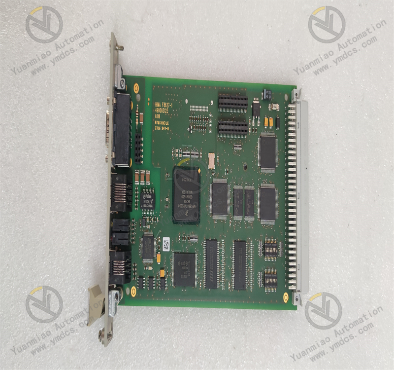
Functional Features: Signal Processing Capability: It can receive, process, and transmit various electrical signals, such as analog signals and digital signals, to achieve precise control and monitoring of related equipment. Communication Function: It supports specific communication protocols and can interact and communicate with other devices or systems, enabling integration into larger automation control systems. Reliability and Stability: It follows ABB's high-quality standards, has high reliability and stability, and can operate stably for a long time in harsh industrial environments. Precise Control: It is used for precisely controlling certain parameters in power systems or specific variables in industrial processes to ensure the efficient operation of the system and the consistency of product quality.
Application Areas: Power System: It can be used in automation control systems of substations, power plants, etc., to achieve monitoring, control, and protection of power equipment. For example, it can monitor and control the status of high-voltage switchgear, transformers, etc., to ensure the stable operation of the power system and reliable power supply. Industrial Automation Production Line: In various automation production lines such as automotive manufacturing, mechanical processing, and electronic device production, it can be part of the control system to control equipment such as motors, frequency converters, and robots on the production line, achieving automated control and coordinated operation of the production process, and improving production efficiency and product quality. Process Industry: In industries such as chemical, petroleum, natural gas, and water treatment, it is used for precisely measuring and controlling various parameters (such as temperature, pressure, flow, liquid level, etc.) in the production process to ensure the safety, stability, and efficiency of the production process, and to achieve the goals of optimized production, energy conservation, and emission reduction. Elevator Control System: It plays a role in the elevator control system, being responsible for functions such as elevator operation control, floor positioning, and safety protection, ensuring the safe and reliable operation of the elevator and a comfortable riding experience.
Installation and Debugging Steps of ABB 07EA90 - SI GJR5251200R0101 in General: Installation Steps 1. Preparation Work Confirm that the installation environment meets the requirements, including conditions such as temperature, humidity, and dust. Installation in places with high temperature, humidity, dust, or corrosive gases should be avoided. Prepare the required tools, such as screwdrivers and wrenches. Ensure that the installers have relevant electrical knowledge and safety awareness, and are familiar with the safety specifications for equipment installation. 2. Appearance Inspection Before installation, carefully check whether the appearance of the equipment is damaged, deformed, or missing parts. If there are any problems, contact the supplier in a timely manner for handling. 3. Determination of Installation Location According to the usage requirements of the equipment and the actual situation on site, determine a suitable installation location. Usually, a place with good ventilation, convenient operation, and maintenance should be selected. At the same time, the spacing between other equipment should be considered to ensure heat dissipation and maintenance space. 4. Fixed Installation Use appropriate installation brackets or bases to fix the ABB 07EA90 - SI GJR5251200R0101 at the selected location. Ensure that the installation is firm to prevent loosening or vibration during operation. According to the installation holes of the equipment, use bolts or screws to fasten it. Pay attention that the tightening torque should meet the requirements of the equipment to avoid being too tight or too loose. 5. Electrical Connection Carefully read the equipment manual to determine the location and specifications of the power input and output interfaces. When connecting the power cord, ensure that the power supply voltage is consistent with the rated voltage of the equipment and that the wiring is correct. Generally, the power cord should be connected to the designated power input terminal of the equipment, and an appropriate wire specification should be used to meet the current-carrying requirements of the equipment. For equipment with signal input and output interfaces, correctly connect the relevant signal lines, such as sensor signal lines and control signal lines, according to the actual application requirements. Pay attention to the shielding and grounding of the signal lines during connection to prevent electromagnetic interference. After all electrical connections are completed, check again whether the wiring is firm and whether there are any loose or poor contact conditions.
Debugging Steps
1. Pre-power-on Inspection
Before powering on for debugging, check again whether the installation and electrical connections of the equipment are correct.
Check whether the parameter settings of the equipment meet the actual application requirements, such as the types, ranges of input and output signals, communication parameters, etc. If the equipment has default parameters, they can be modified and adjusted as needed.
2. Power-on Test
Close the power switch to power on the equipment. Observe whether the power indicator of the equipment lights up normally. If there is any abnormality, cut off the power immediately and check whether there are faults in the power connection and the equipment.
Check whether the initialization process of the equipment is normal. Some equipment may perform self-check or initialization operations after powering on. At this time, pay attention to observing the status display or indicator light changes of the equipment to determine whether the initialization is successful.
3. Basic Function Test
According to the functional characteristics of the equipment, conduct basic function tests. For example, if it is a controller, input some analog signals or digital signals to check whether the equipment can correctly receive and process these signals, and output corresponding control signals according to the preset logic.
For equipment with communication functions, try to conduct communication tests with other related equipment to check whether the communication is normal and whether the data transmission is accurate. The communication function can be verified by sending and receiving test data.
4. Parameter Adjustment and Optimization
Adjust and optimize the parameters of the equipment according to the actual application situation. For example, adjust the control parameters to achieve better control effects, and optimize the communication parameters to improve communication efficiency and stability.
During the parameter adjustment process, it should be carried out step by step. Observe the operation status and performance changes of the equipment after each adjustment to ensure that the adjusted parameters meet the requirements of the system.
5. System Joint Debugging
If the ABB 07EA90 - SI GJR5251200R0101 is integrated into a larger system, joint debugging with other devices or systems is required. During the joint debugging process, closely monitor the operation of the entire system and check whether the collaborative work between the equipment is normal.
Simulate various actual working conditions to check the performance and stability of the equipment under different working conditions, such as full-load operation, partial-load operation, and abnormal situation handling, etc. If there are any problems, analyze and solve them in a timely manner. It may be necessary to further adjust the parameters of the equipment or the configuration of the system.
6. Acceptance and Record
After the debugging is completed, carry out the final acceptance work to confirm whether the equipment meets all the technical requirements and application needs.
Organize the relevant data and records during the debugging process, including the parameter settings of the equipment, test results, problem handling situations, etc., for future maintenance and reference.