Description
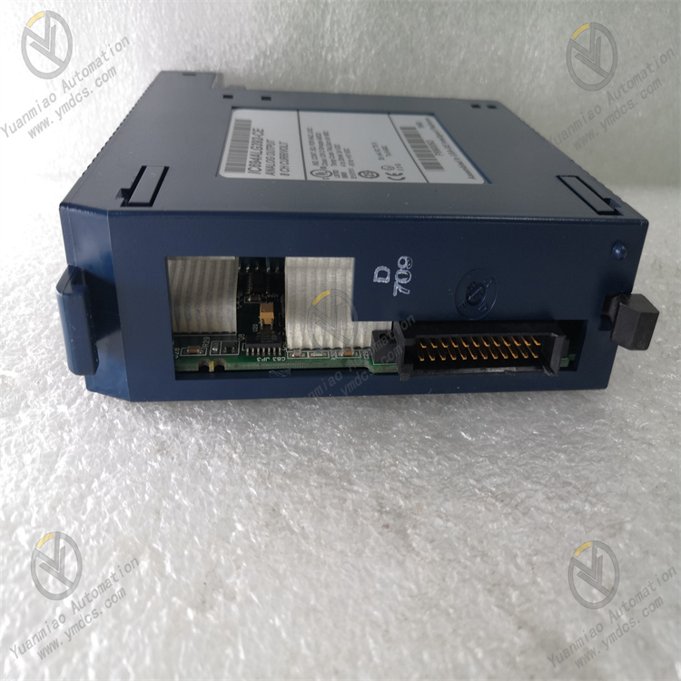
GE IC694ALG392
I. Overview
The GE IC694ALG392 is a combined analog input/output (I/O) module for the RX3i series, specifically designed for the accurate acquisition and reliable control of multiple types of analog signals in industrial automation scenarios. As a key peripheral module of the RX3i system, it integrates both analog input and output functions into one unit. It can directly connect to sensors (for temperature, pressure, flow, etc.) and actuators (such as control valves and frequency converters), eliminating the need to configure separate input and output modules and significantly simplifying the system architecture.
Adopting 16-bit high-precision data conversion technology and an industrial-grade anti-interference design, this module is suitable for fields with strict requirements on signal processing accuracy and stability, including electric power, chemical engineering, intelligent manufacturing, and metallurgy. It can seamlessly collaborate with the CPU via the RX3i system bus, providing efficient signal processing support for the closed-loop control of industrial processes.
II. Technical Parameters
| Parameter Category | Specific Parameters | Parameter Description |
|---|---|---|
| Power Parameters | Input Voltage: DC 5V (powered by RX3i backplane); Rated Power Consumption: ≤10W; Power Ripple Tolerance: ≤150mVpp | Relies on centralized power supply from the system backplane. The low-power design reduces module heat generation, and strong ripple tolerance ensures stable power supply. |
| Analog Input Parameters | Number of Channels: 8; Input Types: 4-20mA DC, 0-20mA DC, 0-10V DC (configurable per channel); Resolution: 16-bit; Accuracy: ±0.05% FS; Sampling Rate: 100Hz per channel (synchronous sampling); Isolation: Optoelectronic isolation between channels, isolation voltage 2500Vrms | Multiple input types adapt to different sensors. High precision and high sampling rate ensure signal acquisition quality, and the isolation design enhances anti-interference capability. |
| Analog Output Parameters | Number of Channels: 4; Output Types: 4-20mA DC, 0-20mA DC, 0-10V DC (configurable per channel); Resolution: 16-bit; Accuracy: ±0.1% FS; Load Capacity: Current output ≤600Ω, Voltage output ≥10kΩ; Response Time: ≤1ms | Flexible output types adapt to actuators. High-precision output ensures control accuracy, and fast response meets real-time control requirements. |
| Operating Environment | Operating Temperature: 0℃~60℃; Storage Temperature: -40℃~85℃; Relative Humidity: 5%~95% (no condensation); Protection Class: IP20 (unit itself); EMC Compliance: Conforms to IEC 61000-4-2/3/4/6 standards | Adapts to the installation environment inside control cabinets. Strong EMC performance resists interference in industrial sites, and the wide temperature and humidity range improves environmental adaptability. |
| Compatibility & Installation | Compatible System: GE RX3i series PLC; Installation Method: RX3i standard backplane mounting; Module Dimensions: 100mm×160mm×30mm (L×W×H); Weight: ≤250g | Seamless compatibility with the RX3i system. The standard installation method facilitates deployment and maintenance, and the compact structure saves space inside the cabinet. |
III. Functional Features
- High-Precision Analog Signal Processing: The analog input channels use 16-bit high-precision A/D converters, combined with hardware filtering and software noise reduction algorithms, to achieve an acquisition accuracy of ±0.05% FS, enabling accurate capture of tiny signal changes in industrial sites. The analog output channels adopt 16-bit D/A converters, with an output accuracy of ±0.1% FS, which can provide stable control signals for actuators and ensure the accuracy of closed-loop control. The synchronous sampling rate of 100Hz per channel ensures the time consistency of multi-channel signal acquisition, making it suitable for multi-parameter collaborative control scenarios.
- Flexible Channel Configuration Capability: All 8 analog input channels and 4 analog output channels support independent per-channel configuration. According to the types of on-site sensors and actuators, input channels can be separately set to 4-20mA, 0-20mA, or 0-10V types, and the same applies to output channels. It can adapt to devices with different signal types without replacing the module, greatly improving the module's versatility and the flexibility of system configuration, while reducing equipment procurement and maintenance costs.
- Strong Anti-Interference and High-Reliability Design: It adopts an optoelectronic isolation design between channels, with an isolation voltage of 2500Vrms, which can effectively block interference signals between channels and resist common-mode and differential-mode interference in industrial sites. The module integrates surge protection and overcurrent protection circuits; when the input signal exceeds the limit or the output is short-circuited, it can automatically disable part of the functions of the faulty channel to protect the module and external equipment from damage. Using industrial-grade high-quality components, it has passed strict high-low temperature cycling and vibration impact tests, with a Mean Time Between Failures (MTBF) of over 180,000 hours.
- Seamless System Integration and Collaborative Control: As a dedicated module for the RX3i series, it can be seamlessly connected to the CPU module via the RX3i standard backplane, requiring no additional adapter circuits and supporting plug-and-play. The module interacts with the CPU in real time via the system bus: collected analog signals are quickly uploaded to the CPU for calculation, and control commands issued by the CPU can be rapidly converted into analog signals for output by the module, with a response time of ≤1ms, ensuring the real-time execution of control commands. It supports collaborative work with other RX3i series modules (such as digital I/O and communication modules) to form a complete control system.
- Convenient Diagnostics and Maintenance Functions: It is equipped with comprehensive self-diagnostic functions that can real-time monitor the module's power supply status, channel signal integrity, and the working status of A/D/D/A conversion circuits. When a fault is detected (such as channel overload or conversion error), it outputs a fault code through the flashing of the module's panel indicator lights and uploads the fault information to the CPU, facilitating engineers to quickly locate the faulty channel and fault type. It supports online configuration and status monitoring via GE Proficy Machine Edition programming software, allowing intuitive viewing of real-time signal values and configuration parameters of each channel, enabling parameter adjustment and fault troubleshooting without disassembling the module on-site.
IV. Working Principle
As a combined analog I/O module, the core function of the GE IC694ALG392 is to realize the "acquisition-conversion-transmission" of analog signals and the "reception-conversion-output" of control signals, collaborating with the CPU to complete closed-loop control. The specific working principle is as follows:
- Module Initialization and Configuration Loading: After the module is installed on the RX3i backplane, it is connected to the DC 5V power supply and establishes communication with the CPU. The CPU issues module configuration parameters (such as input/output type, range, and sampling rate for each channel) via the system bus, and the module completes initialization after loading the configuration. During the initialization phase, it performs a self-test on the internal A/D, D/A conversion circuits, and isolation circuits; if the self-test passes, the "OK" indicator on the panel remains on; if the self-test fails, the "FAULT" indicator flashes and reports fault information.
- Analog Signal Acquisition and Conversion: The analog input channels real-time receive analog signals output by sensors (such as 4-20mA current signals and 0-10V voltage signals). The signals first pass through a surge protection circuit to filter out peak interference, then enter the optoelectronic isolation circuit to achieve electrical isolation between channels and avoid interference crosstalk. The isolated signals are sent to a 16-bit A/D converter to convert the analog signals into digital signals. Subsequently, hardware filtering circuits and software algorithms further eliminate noise to improve signal stability. The converted digital signals are stored in the module's internal buffer according to channel addresses, waiting for the CPU to read them.
- Data Transmission and Command Reception: The CPU reads the collected data from the module's buffer via the system bus at a preset cycle and stores it in the CPU's input data image area for subsequent program calculations. At the same time, the CPU issues control commands (digital quantities) generated by calculations to the module; the module stores the commands in the output buffer after reception, waiting for conversion and output. A verification mechanism is used during data transmission to ensure the integrity and accuracy of data transmission.
- Analog Signal Conversion and Output: The module reads the digital control commands from the output buffer and sends them to a 16-bit D/A converter to convert the digital signals into corresponding analog signals (such as 4-20mA current or 0-10V voltage). The converted analog signals undergo power amplification through a signal amplification circuit and an output drive circuit to meet the load requirements of the actuator. During the output process, the module real-time monitors the amplitude of the output signal and the load status; if an output short circuit or overload is detected, it immediately activates the protection mechanism, disables the output of that channel, and reports the fault.
- Status Monitoring and Fault Feedback: During operation, the module real-time monitors its own working status (power supply voltage, internal temperature) and the status of each channel (input signal amplitude, output load). When abnormal conditions such as input signal over-range, output short circuit, or conversion circuit failure are detected, it immediately records the fault information (faulty channel, fault type), displays the fault status via the panel indicator lights, and uploads the fault data to the CPU, providing a basis for system fault diagnosis.
V. Common Faults and Solutions
| Fault Phenomenon | Possible Causes | Solutions |
|---|---|---|
| Module unresponsive, all indicators off | 1. Backplane power supply fault, no DC 5V voltage provided; 2. Poor contact between module and backplane; 3. Damage to the module's internal power circuit | 1. Use a multimeter to measure the voltage of the backplane power supply terminal to confirm if it is DC 5V±0.2V; if abnormal, replace the backplane or system power module; 2. Power off, reinsert the module, and clean the contacts between the module and the backplane; 3. Test with a spare module and contact GE after-sales service to repair the faulty module |
| Large deviation or instability of analog input data | 1. Sensor fault or incorrect signal wiring; 2. Signal wires not using shielded cables or ungrounded shield layer; 3. Input channel not calibrated or lost calibration parameters; 4. Severe electromagnetic interference on-site | 1. Replace with a spare sensor and check the positive and negative wiring of the signal wires; 2. Replace with shielded twisted-pair cables and reliably ground the shield layer at one end (ground resistance ≤4Ω); 3. Recalibrate the input channel via programming software and restore calibration parameters; 4. Adjust the module's installation position to keep it away from interference sources such as frequency converters and high-power motors; install a signal isolator if necessary |
| No analog output signal or unstable output signal | 1. Loose, broken, or incorrect output signal wiring; 2. Actuator fault or load exceeding the module's output capacity; 3. Output channel fault or abnormal D/A conversion circuit; 4. Control commands not issued or incorrect parameter configuration | 1. Check the connection of the output signal wires to ensure firm contact and correct wiring; replace broken wires; 2. Disconnect the output signal wires and use a multimeter to measure the signal at the module's output terminals; if normal, the fault lies with the actuator—check the actuator's power supply and itself; if the output signal is abnormal, confirm that the load is ≤600Ω (for current output) or ≥10kΩ (for voltage output), and test after reducing the load; 3. Test with a spare channel; if the fault persists, it is an internal module fault—contact after-sales service; 4. Monitor the control command issuance status via programming software and check the channel output type and range configuration parameters |
| Module "FAULT" light flashing, reporting "channel overload" fault | 1. Input signal of the analog input channel exceeds the range; 2. Short circuit or overload of the analog output channel load; 3. Abnormal sensor output (e.g., short circuit); 4. Fault of the module's channel protection circuit | 1. Use a multimeter to measure the amplitude of the input signal to confirm if it is within the configured range; replace the sensor that exceeds the range; 2. Check if the output circuit is short-circuited, measure the load resistance, and ensure the load is within the module's allowable range; 3. Disconnect the sensor from the module, measure the sensor's output, and replace the sensor if faulty; 4. If the above measures are ineffective, replace the module and contact after-sales service for repair |
| CPU unable to read module data or issue commands | 1. Poor contact between module and backplane; 2. Incorrect module address configuration, conflicting with other modules; 3. System bus fault or backplane damage; 4. Fault of the module's communication circuit | 1. Power off, reinsert the module, and clean the contacts; 2. View the module address via programming software and modify the conflicting address to a unique one; 3. Replace the module to another backplane slot for testing; if the fault persists, replace the backplane; 4. Test with a spare module and contact after-sales service to repair the faulty module |