Description
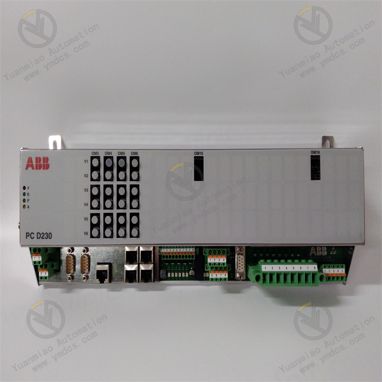
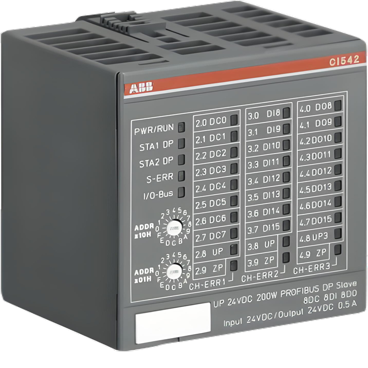
ABB CI542-DP 1SAP224200R0001
The ABB CI542-DP 1SAP224200R0001 is an interface module applied in the field of industrial automation.
Functional Features
- As a PROFIBUS slave station, it enables communication with PROFIBUS master station devices, facilitating data interaction and equipment control in industrial networks.
- It has 8 digital inputs with 24VDC, 8 digital outputs with 24VDC 0.5A, and 8 digital input/output pins configurable as 24VDC 0.5A, flexibly meeting the digital input/output control requirements in different industrial scenarios.
Hardware Interfaces
- Equipped with 1 RS-485 interface for communication and data transmission with other devices supporting this interface.
Electrical Characteristics
- Input voltage: 24V DC, input current: 5 mA.
- Power supply voltage range: 20.4–28.8V DC. The output is transistor-based, with an output current of 0.5A, a maximum output voltage of 20.4–28.8V, and a delay time of 0.1–32 ms, enabling stable operation in various industrial power environments.
Physical Characteristics
- Net depth/length: 62 mm, net height: 76 mm, net width: 67.5 mm, gross weight: 0.154 kg. Its compact size facilitates installation in various industrial control cabinets or equipment.
- Protection level: IP20, which can prevent external objects and dust from entering to a certain extent, suitable for general industrial environments.
Scalability
- It can expand up to 10 I/O modules, allowing users to flexibly expand the input/output points of the system according to actual application needs to meet more complex control tasks.
Operation Guide for ABB CI542-DP (1SAP224200R0001)
1. Installation and Connection
1.1 Pre-installation Inspection
- Confirm that the module has no physical damage, and the pins are not bent or oxidized.
- Check whether accessories (such as terminal blocks and screws) are complete.
- Verify that the module model matches the application requirements (PROFIBUS slave station, digital I/O configuration).
1.2 Mechanical Installation
- Rail Mounting: Use a standard DIN rail to ensure the module is firmly clipped into the rail.
- Space Requirements: Leave at least 10mm clearance on both sides of the module and 50mm heat dissipation space at the top.
- Orientation Limitations: Horizontal installation is recommended. For vertical installation, ensure the ambient temperature does not exceed 40°C (derating may be required otherwise).
1.3 Electrical Connections
- Power Connection:
- Connect a 24V DC power supply (within the range of 20.4–28.8V).
- Pay attention to polarity: L+ (positive) connects to the power supply positive, and M (negative) connects to the power supply negative.
- The power supply fluctuation should be less than ±10%, and an isolated power supply is recommended.
- PROFIBUS Communication Connection:
- Use the RS-485 interface to connect to the PROFIBUS network.
- Follow PROFIBUS bus topology rules (terminal resistance, cable type, segment length).
- Terminal stations need to activate the terminal resistance (usually set via a DIP switch on the module).
- Digital I/O Connection:
- Input Signals: Connect 24V DC signal sources to the DI terminals (8 independent inputs).
- Output Signals: Connect loads (such as relays and indicator lights) to the DO terminals (8 outputs with 0.5A).
- Shared Input/Output Terminals: Set as DI or DO mode via configuration software (8 configurable channels).
2. Parameter Configuration
2.1 PROFIBUS Slave Station Setup
- Station Address Setting:
- Set a unique PROFIBUS station address (range: 1–126) via the DIP switch (usually 5-bit) on the module.
- Example: Switches 1–5 correspond to binary bits, and the station address = binary value + 1 (e.g., all OFF = address 1, all ON = address 31).
- Baud Rate Configuration:
- Set the baud rate (9.6kbps–12Mbps) via software or the DIP switch according to the master station device.
- Ensure consistency with other devices in the PROFIBUS network.
2.2 Digital I/O Configuration
- I/O Mode Setting:
- Open the device configuration interface and select the CI542-DP module.
- Set the 8 configurable pins to DI (digital input) or DO (digital output) mode.
- Example: If more input points are needed, some IO terminals can be configured as DI mode.
- Use ABB’s configuration tools (such as Automation Builder or Control Builder):
- Input Filter Setting:
- Adjust the input signal filtering time (0.1–32ms) to resist interference (such as mechanical contact bounce).
- Set the filtering parameters for each DI channel via configuration software.
3. Function Testing
3.1 Power Test
- After powering on, observe the module’s LED indicators:
- PWR Light: Steady green indicates normal power supply.
- BF Light: Red flashing indicates a bus fault (check PROFIBUS connections).
- RUN Light: Green flashing indicates normal module operation.
3.2 PROFIBUS Communication Test
- Use PROFIBUS diagnostic tools (such as Siemens SIMATIC NCM):
- Scan the network to confirm that the CI542-DP module is recognized and the station address is correct.
- Monitor communication quality (e.g., signal strength, bit error rate).
- Data Exchange Test:
- Send test data from the master station to the module’s input registers.
- Use output registers to control DO terminals and verify load actions.
3.3 Digital I/O Test
- Input Test:
- Short the DI terminal to the 24V DC power supply and observe the change in the module’s LED status.
- Monitor whether the values in the input registers change correspondingly via configuration software.
- Output Test:
- Write values to the DO registers via software (e.g., 0xFF to activate all outputs).
- Use a multimeter to measure the voltage at the DO terminals (24V DC indicates activation).
4. Fault Troubleshooting
4.1 Common Faults and Solutions
| Fault Phenomenon | Possible Causes | Solutions |
|---|---|---|
| No power to the module | Power not connected or polarity error | Check power connections and measure input voltage (20.4–28.8V). |
| PROFIBUS communication failure | Station address conflict, bus short circuit, incorrect terminal resistance setting | Reset the station address, check cable connections, and confirm the terminal resistance status (only activate at both ends of the segment). |
| No response from digital input | Input signal below the threshold (需≥15V DC) | Check the input signal voltage, clean the terminal oxidation layer, and adjust the filtering time. |
| Digital output cannot drive the load | Load current exceeds 0.5A, output short circuit | Replace with a low-power load, check the output circuit for short circuits, and use external relays to expand current capacity. |
| Abnormal LED indicators | Module hardware failure | Power off and restart the module. If the issue persists, contact ABB technical support for replacement. |
4.2 Diagnostic Tools
- LED Indicators: Refer to the LED status table in the module manual to quickly locate fault types.
- ABB Diagnostic Software: Read module diagnostic information (such as I/O status and error codes) via Automation Builder.
- PROFIBUS Multimeter: Detect bus voltage, terminal resistance value, and signal quality.
5. Maintenance and Precautions
- Regular Inspections:
- Check terminal tightness every 6 months to prevent poor contact due to looseness.
- Clean dust from the module surface to ensure good heat dissipation.
- Environmental Requirements:
- Operating temperature: -25°C~+60°C (horizontal installation), -25°C~+40°C (vertical installation).
- Humidity: 5%~95% RH (non-condensing).
- Avoid installation in strong electromagnetic fields or vibrating environments.
- Safety Precautions:
- Operate after powering off to avoid electric shock.
- Ensure the master station has stopped communication before replacing the module to prevent data conflicts.
- When troubleshooting, prioritize checking power and communication connections rather than replacing the module directly.