Description
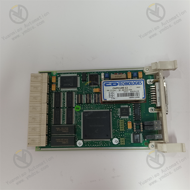
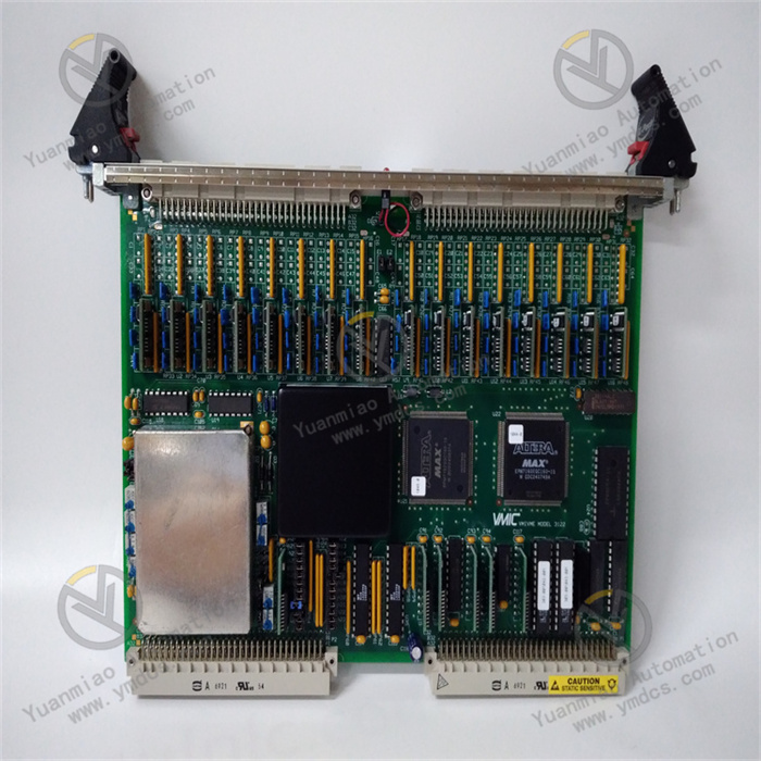
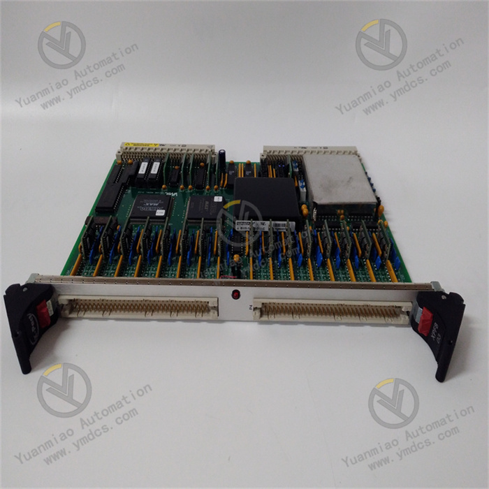
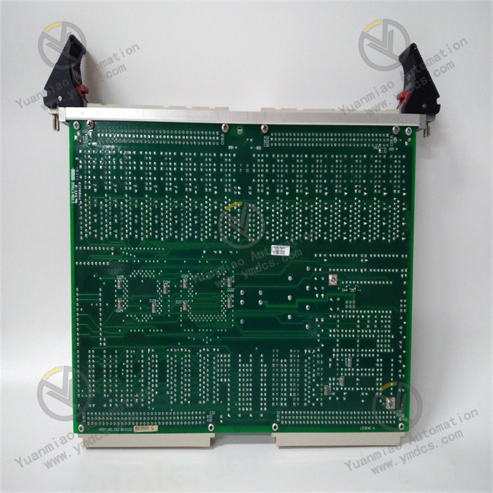
GE VMIVME-3122
I. Overview
The VMIVME-3122 by Abaco Systems is a high-resolution analog input board designed for VMEbus system applications. It entered the Restricted Production Phase (RPP) on November 5, 2008. Despite being in this phase, it still plays a crucial role in numerous industrial and scientific research fields. With its 16-bit digitization resolution, programmable gain, selectable conversion rate, and automatic scanning function for 64 differential or single-ended analog inputs, this board provides users with an excellent dynamic range and extremely high analog input channel density, performing outstandingly in system applications such as factory automation, process control, data acquisition systems, training simulators, and laboratory instruments.
II. Functional Features
(1) High-Resolution Analog-to-Digital Conversion
Equipped with a high-performance 16-bit analog-to-digital converter (ADC), it accurately converts analog signals into digital signals, providing a reliable foundation for subsequent data processing and analysis. This high resolution ensures precise capture of input signal details, making it suitable for application scenarios with strict signal accuracy requirements, such as monitoring tiny signal changes in scientific research experiments.
(2) Abundant Input Channels and Flexible Scanning Modes
- Numerous Input Channels: Features 64 input channels, supporting both differential and single-ended input modes. Differential input effectively suppresses common-mode interference, ensuring accurate signal acquisition in complex electromagnetic environments; single-ended input is suitable for cost-sensitive scenarios with minimal interference.
- Flexible Scanning Options: Supports program-selectable scanning modes, allowing users to choose to scan 1, 8, 16, 32, 48, or 64 channels based on actual needs. For example, in factory automation, if only partial parameters of key equipment need monitoring, scanning a small number of channels can improve data acquisition efficiency; for comprehensive data acquisition tasks, full-channel scanning can be selected.
(3) Configurable Conversion Rate
The software-selectable conversion rate can reach up to 100kHz, enabling users to flexibly adjust it according to the real-time requirements of specific application scenarios. In industrial control systems requiring fast response, the conversion rate can be set to a higher value to promptly obtain the latest sensor data; in monitoring tasks with slow data changes, reducing the conversion rate can minimize system resource consumption.
(4) Multiple Working Modes
- Scanning Modes: Offers three scanning modes to facilitate different application needs:
- Automatic Scanning Mode: The board periodically scans selected channels according to preset sequences and parameters, suitable for routine data acquisition tasks.
- Data Burst Mode: Enables rapid collection of large amounts of data in a short time, meeting the need to capture instantaneous signal changes, such as in impact test experiments.
- External Synchronization Mode: Enables the board to perform synchronous data acquisition with external devices, ensuring data consistency among multiple devices, which is crucial in systems with multi-device collaborative work.
- Trigger Modes: Also has three trigger modes to initiate data acquisition based on different conditions, such as triggering on the rising or falling edge of a specific external signal, or automatically triggering at a preset time interval. This makes data acquisition more intelligent and precise, avoiding unnecessary data collection and saving system resources.
(5) Other Features
- Dual-Port Data Memory: Facilitates fast data storage and reading. On one hand, it allows the board to temporarily store data in a timely manner during data acquisition; on the other hand, it enables the host processor to efficiently retrieve data, reducing data transmission latency and enhancing the overall data processing efficiency of the system.
- On-Board Timer: Used to precisely control the time interval and timing of data acquisition, ensuring the accuracy and stability of data collection. For example, in periodic data acquisition tasks, the on-board timer ensures that the time interval between each acquisition is strictly consistent.
- Automatic Gain Control: Automatically adjusts the gain according to the size of the input signal, enabling the ADC to better adapt to input signals of different amplitudes. This ensures that small signals can be accurately identified while avoiding overload of large signals, thereby improving the dynamic range and accuracy of signal acquisition.
- Programmable Bus Interruptor: When data acquisition is completed or a specific event occurs, it sends an interrupt signal to the host processor to notify the host for corresponding processing. This reduces the polling overhead of the host for data acquisition status and improves the real-time response capability of the system.
- Optional Low-Pass Filter: Filters input analog signals to remove high-frequency noise interference, making the acquired signals purer and improving data reliability, especially in industrial environments where signals are susceptible to high-frequency noise pollution.
III. Working Principle
(1) Signal Acquisition and Conversion
- Analog Signal Input: External analog signals are connected to the board through a 96-pin non-locking connector, with the option of differential or single-ended input. In differential input, the voltage difference between two pins is used as the effective signal, which can effectively suppress common-mode interference and improve signal anti-interference capability; single-ended input uses the voltage between one pin and the common ground as the signal.
- Signal Conditioning: The input analog signal first passes through an automatic gain control circuit, which adjusts the gain automatically according to the signal amplitude to ensure the signal is within the optimal input range of the ADC. Then, if the user has selected a low-pass filter, the signal passes through this filter to remove high-frequency noise, ensuring the signal quality input to the ADC.
- Analog-to-Digital Conversion: The conditioned analog signal enters the 16-bit ADC for analog-to-digital conversion. The ADC converts the analog signal into the corresponding 16-bit digital signal according to the signal amplitude. During the conversion process, the conversion rate is determined by software settings, up to 100kHz.
(2) Data Storage and Transmission
- Dual-Port Data Memory: The converted digital signals are temporarily stored in the dual-port data memory. The dual-port design allows the board to store data while the host processor reads data from the other port, enabling parallel operations of data storage and reading to improve data processing efficiency.
- Scanning and Trigger Control: The board controls the ADC to scan and acquire data for selected input channels according to the user-set scanning mode (automatic scanning, data burst, or external synchronization) and trigger mode (such as level trigger, edge trigger, timing trigger, etc.). During scanning, the number of scanned channels (1, 8, 16, 32, 48, or 64 channels) can be selected through programming.
- Data Transmission and Interrupt: When data acquisition is completed or specific interrupt conditions are met (such as the data buffer being full or a specific scan being completed), the programmable bus interruptor sends an interrupt signal to the host processor. Upon receiving the interrupt signal, the host reads data from the dual-port data memory through the VMEbus for subsequent processing and analysis. Meanwhile, the on-board timer is used to precisely control the time interval of scanning and data acquisition, ensuring the timing accuracy of the entire process.
IV. Common Faults and Solutions
(1) Abnormal Data Acquisition
- Possible Causes:
- Signal connection issues: Input signal cables are open, short-circuited, or have poor contact, preventing signals from being transmitted to the board normally.
- Channel configuration errors: Users have incorrect settings for acquisition channels, such as selecting non-existent channels or mistakenly setting the input mode (differential/single-ended).
- ADC failure: Long-term use or electromagnetic interference causes the ADC chip to degrade or be damaged, making it unable to perform analog-to-digital conversion normally.
- Solutions:
- Check signal connections: Carefully inspect input signal cables to ensure they are firmly connected without open or short circuits. If necessary, replace the cables for testing.
- Verify channel configuration: Recheck channel configuration parameters to ensure they match the actual connected signals and application requirements. Refer to the board's user manual to correctly set the number of channels, input mode, and other parameters.
- Test the ADC chip: Use professional testing tools to detect the ADC chip. If the chip is faulty, contact Abaco Systems' technical support or professional maintenance personnel for replacement.
(2) Abnormal Conversion Rate
- Possible Causes:
- Software setting errors: Users enter values beyond the board's supported range when setting the conversion rate, or make incorrect operations during the setting process.
- System resource conflicts: In the VMEbus system where the board is located, other devices compete for system resources with the VMIVME-3122, causing the conversion rate to fail to meet expectations.
- Hardware failure: The circuit components responsible for controlling the conversion rate on the board fail, affecting the normal adjustment of the conversion rate.
- Solutions:
- Verify software settings: Reconfirm the software settings for the conversion rate to ensure they are within the board's supported range (up to 100kHz), and follow the correct operation 流程 to set them. Refer to the software operation manual or consult technical support personnel.
- Troubleshoot system resource conflicts: Check the configuration and working status of other devices in the VMEbus system. Try to turn off or reconfigure potentially conflicting devices, then test the conversion rate again. If the problem persists, contact the system integrator or relevant technical experts to optimize system resource allocation.
- Repair hardware circuits: For hardware failures, professional maintenance personnel need to use professional tools to detect the board, locate, and replace faulty circuit components. It is recommended to back up important data in the board before sending it for repair.
(3) Abnormal Working Mode
- Possible Causes:
- Mode setting errors: Users operate improperly when setting the scanning mode or trigger mode, resulting in the mode settings not taking effect or being set incorrectly.
- Abnormal external trigger signal: When using the external trigger mode, the external trigger signal is input without following the expected level, edge, or timing, causing the board to fail to respond correctly.
- Internal logic failure of the board: The logic circuit responsible for controlling the working mode inside the board fails, unable to correctly execute the mode set by the user.
- Solutions:
- Reset the working mode: Carefully read the board's user manual and reset the scanning mode and trigger mode according to the correct steps. After setting, conduct relevant tests to observe whether the board works in the set mode.
- Check the external trigger signal: Use tools such as an oscilloscope to check whether the level, edge, and timing of the external trigger signal meet the board's requirements. If the signal is abnormal, inspect the output of the external signal source or related connection lines to ensure the trigger signal is normal.
- Repair the board's logic circuit: For internal logic failures of the board, send the board to a professional maintenance institution or Abaco Systems' after-sales service center for repair. Maintenance personnel will use professional equipment to detect and repair the logic circuit.
(4) Communication Failure with the VMEbus System
- Possible Causes:
- Bus connection issues: The VMEbus connector is loose or has poor contact, or the bus cable is damaged, causing data transmission interruption between the board and the system.
- Address conflict: The address setting of the VMIVME-3122 in the VMEbus system conflicts with other devices, making the system unable to correctly identify the board.
- Board communication interface failure: The VMEbus communication interface circuit on the board fails, unable to send and receive data normally.
- Solutions:
- Check bus connections: Inspect the VMEbus connector to ensure it is firmly connected without looseness. If necessary, re-plug the connector. Meanwhile, check whether the bus cable is damaged, and replace the cable promptly if any issues are found.
- Resolve address conflicts: View the address settings of all devices in the VMEbus system to ensure the address of the VMIVME-3122 is unique and does not conflict with other devices. If a conflict exists, reset the board's address to make it unique within the system address range.
- Repair the communication interface failure: For communication interface failures of the board, professional technicians need to use professional tools to detect and repair the communication interface circuit. If repair is not possible, consider replacing the board with a new one.