Module")
 Module")
 Module")
Description
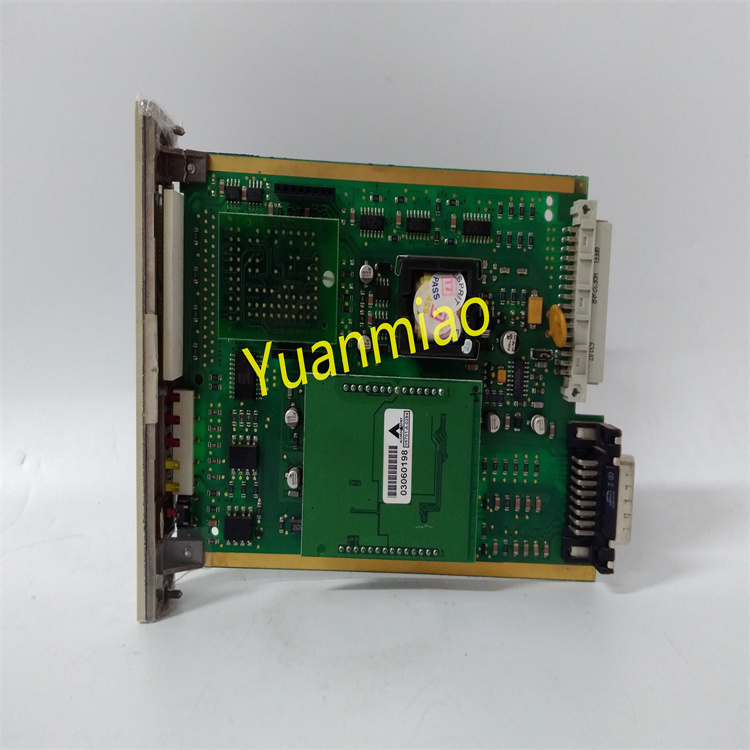
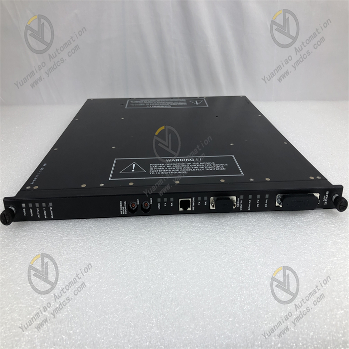
GE IC200BEM003
I. Overview
The GE IC200BEM003 is a bus expansion module for the VersaMax series programmable logic controllers (PLCs). Its core function is to enable rack expansion of the control system via the VersaMax Local Bus, addressing issues such as insufficient I/O points in a single rack or decentralized equipment deployment.
Adopting an industrial-grade modular design, this module features a compact structure, stable bus transmission performance, and excellent compatibility. It is widely used in small and medium-sized industrial automation scenarios, including machinery manufacturing, food processing, warehousing and logistics, and small-scale chemical equipment.
As the expansion core of the VersaMax system, it enables high-speed data interaction between the main rack and expansion racks, supporting up to 3 slave racks for expansion. This significantly enhances the flexibility of system I/O configuration and provides an efficient bus connection solution for decentralized control scenarios.
II. Technical Specifications
| Specification Category | Specific Parameters | Parameter Description |
|---|---|---|
| Power Supply Parameters | Input Voltage: DC 5V (powered by VersaMax rack power module); Rated Power Consumption: ≤5W; Power Ripple Tolerance: ≤100mVpp | Relies on centralized system power supply. The low-power design reduces module heat generation, and strong ripple tolerance ensures stable bus transmission. |
| Bus Performance | Bus Type: VersaMax Local Bus; Transmission Rate: 1Mbps; Maximum Transmission Distance: 30 meters (single segment); Supported Expansion Racks: Up to 3 | High-speed bus transmission meets real-time data interaction requirements. The 30-meter transmission distance is suitable for decentralized deployment in small and medium-sized workshops. |
| Expansion Capacity | Maximum I/O Modules per Expansion Rack: 8; Supported Module Types: VersaMax series digital I/O, analog I/O, and special function modules; Maximum Expandable I/O Points: 512 digital points, 64 analog points | Rich expansion capacity meets control needs of different scales. Compatibility with the full range of modules improves configuration flexibility. |
| Operating Environment | Operating Temperature: 0℃~60℃; Storage Temperature: -40℃~85℃; Relative Humidity: 5%~95% (non-condensing); Protection Class: IP20 (module itself); EMC Immunity: Complies with IEC 61000-4-2/3/4 standards | Suitable for installation inside control cabinets. Strong anti-interference capability ensures stable bus transmission in complex industrial environments. |
| Physical & Installation | Dimensions: 89mm×127mm×25mm (L×W×H); Installation Method: VersaMax standard rack DIN rail mounting; Weight: ≤200g; Bus Connection: Dedicated bus cable (with latch) | The compact structure saves rack space. Standard DIN rail mounting enables quick deployment, and the latched bus cable ensures reliable connection. |
III. Functional Features
- Efficient Bus Expansion & Data Transmission:Adopts VersaMax Local Bus technology with a transmission rate of 1Mbps, enabling real-time data interaction between the main rack CPU and expansion rack I/O modules. The data transmission delay is ≤1ms, meeting the real-time requirements of small and medium-sized control systems. It supports expansion of up to 3 slave racks, with each expansion rack capable of installing 8 I/O modules. The maximum expandable capacity includes 512 digital I/O points and 64 analog I/O points, allowing flexible system capacity expansion based on production scale and avoiding the limitations of single-rack configuration.
- Full-Range Module Compatibility & Flexible Configuration:Fully compatible with all VersaMax series modules, including digital input/output modules, analog input/output modules, high-speed counting modules, temperature acquisition modules, communication modules, and other special function modules. During expansion, there is no need to modify the core logic of the main CPU program. Only the expansion rack address and module mapping relationship need to be configured via programming software to achieve quick access to new modules, significantly improving the efficiency of system upgrading and transformation.
- Reliable Connection & Anti-Interference Design:Uses dedicated latched bus cables for inter-rack connection. The latch structure effectively prevents cable loosening caused by vibration, ensuring mechanical reliability of the bus connection. The module integrates bus signal differential transmission circuits and photoelectric isolation technology, with an isolation voltage of 2500Vrms. This effectively resists electromagnetic interference, common-mode interference, and other interference factors in industrial sites, avoiding bus data transmission errors or loss.
- Convenient Status Monitoring & Diagnostics:The module front panel is equipped with bus communication indicator (BUS ACT), power indicator (PWR), and fault indicator (FAULT), which intuitively display the module's power status, bus communication activity, and fault conditions. When a bus disconnection, expansion module fault, or address conflict occurs, the FAULT indicator flashes to issue an alarm. Meanwhile, the main CPU can read fault information (such as faulty rack number and module address) via the bus, facilitating engineers to quickly locate fault points and reduce maintenance costs.
- Compact Structure & Easy Deployment:Features an ultra-thin and compact design with a thickness of only 25mm, allowing flexible installation in VersaMax standard racks without occupying excessive space. It is suitable for installation in small control cabinets. The module requires no independent programming or complex configuration. After connecting the main and slave racks with a dedicated bus cable, only the expansion rack parameters need to be configured in the CPU programming software to achieve plug-and-play functionality, simplifying the system deployment process.
IV. Working Principle
As a bus expansion module, the core function of the GE IC200BEM003 is to build a communication bridge between the main rack and expansion racks, enabling bidirectional data transmission. The specific working principle is as follows:
- System Initialization & Address Configuration:After the module is installed in the designated slot of the expansion rack (usually the first slot of the rack), it obtains DC 5V power through the rack backplane and then establishes bus communication with the main rack CPU. Engineers assign a unique address (1-3) to each expansion rack via GE programming software (such as VersaPro, Cimplicity Machine Edition). The module stores this address and completes initialization. During initialization, the module detects the bus connection status and the model of each module in the expansion rack, and feeds the detection results back to the main CPU via the bus.
- Data Acquisition & Upload:The I/O modules in the expansion rack (such as digital input modules and analog input modules) collect on-site signals in real time, convert the signals into digital quantities, and store them in the module's internal buffer. The IC200BEM003 reads the data from each module's buffer according to the preset communication cycle (set by the main CPU, minimum 1ms), packages the data in the format of "rack address - module address - channel address" via the VersaMax Local Bus, and uploads it to the input data image area of the main CPU. A CRC check mechanism is used during data transmission to ensure data integrity.
- Control Command Reception & Issuance:After the main CPU executes the control program, it generates control commands and stores them in the output data image area. The IC200BEM003 monitors the bus data sent by the main CPU in real time. When it detects that the target address is the expansion rack where it is located, it parses the control commands in the data package and distributes them to the corresponding output modules (such as digital output modules and analog output modules) in the expansion rack according to the module address and channel address. The output modules drive the actuators to act after receiving the commands, completing the control loop.
- Status Monitoring & Fault Feedback:The module monitors its own power supply status, bus communication rate, data transmission error rate, and the working status of each module in the expansion rack in real time. When faults such as bus disconnection (no communication signal), data transmission error rate exceeding 5%, or unresponsive expansion modules are detected, it immediately triggers a fault alarm: the front-panel FAULT indicator flashes, and at the same time, it packages and uploads fault information (fault type, fault location) to the main CPU. After receiving the information, the main CPU can display the fault information via the HMI or trigger an audible and visual alarm to remind maintenance personnel to handle the issue.
V. Common Faults & Troubleshooting Methods
| Fault Phenomenon | Possible Causes | Troubleshooting Methods |
|---|---|---|
| Power indicator (PWR) is off, and the module is unresponsive | 1. Faulty expansion rack power module, no DC 5V output; 2. Poor contact between the module and rack backplane; 3. Damaged internal power circuit of the module | 1. Use a multimeter to measure the voltage at the rack backplane power terminals to confirm if it is DC 5V±0.2V. Replace the power module if abnormal. 2. Power off, reinsert the module, and clean the module pins and backplane contacts. 3. Test with a spare module and contact GE after-sales service for the faulty module. |
| Bus indicator (BUS ACT) does not flash, no data transmission | 1. Bus cable not properly connected, damaged, or latch not fastened; 2. Incorrect expansion rack address configuration or address conflict with other racks; 3. Faulty main CPU bus interface; 4. Damaged module bus communication circuit | 1. Check the bus cable connection, re-fasten the latch, and test with a spare cable. 2. Verify the expansion rack address via programming software to ensure it is unique within 1-3. 3. Move the main rack bus module to a spare slot for testing; replace the main CPU if ineffective. 4. Test with a replacement module and report the faulty module for repair. |
| Fault indicator (FAULT) flashes, main CPU reports "expansion module communication fault" | 1. A faulty I/O module in the expansion rack or improper installation; 2. Bus transmission distance exceeding 30 meters, causing signal attenuation; 3. Excessive on-site electromagnetic interference leading to data transmission errors; 4. Faulty communication circuit between the module and expansion modules | 1. Reinsert each I/O module in the expansion rack one by one, restart the system to check if the fault disappears, and locate and replace the faulty module. 2. Shorten the bus transmission distance to within 30 meters, or add a signal repeater in the middle of the bus. 3. Replace with a shielded bus cable, ground one end of the cable shield, and keep it away from interference sources such as frequency converters. 4. Test with a replacement bus expansion module. |
| Data cannot be collected or commands cannot be issued for some expansion I/O modules | 1. Poor contact between the faulty module and the rack; 2. Incorrect module address configuration or address conflict with other modules; 3. Damaged faulty module itself; 4. Faulty distribution circuit of the bus expansion module | 1. Power off, reinsert the faulty I/O module, and clean the contacts. 2. Check the module address via programming software and modify it to an unused address. 3. Move the faulty module to the main rack for testing and replace it if confirmed damaged. 4. Replace the bus expansion module and check if the fault is resolved. |
| Unstable data transmission with frequent data loss | 1. Aging bus cable causing signal attenuation; 2. High bus load due to simultaneous communication of multiple expansion racks; 3. Excessive power ripple interfering with bus signals; 4. Poor module heat dissipation leading to unstable operation | 1. Replace with a new dedicated bus cable. 2. Reduce the number of expansion racks communicating simultaneously, or optimize the control program to lower the communication frequency. 3. Check the output ripple of the power module; replace the power module and add a power filter if the ripple exceeds the standard. 4. Clean the control cabinet vents to ensure good module heat dissipation; install an additional cooling fan if necessary. |